Designing Plaza Hardscapes: Considerations from insulation and waterproofing to structural support
By Kurt R. Hoigard, PE, SECB, FASTM, and Brian T. Lammert, SE, PE, CDT
Outdoor plazas provide open spaces that break up the massing of neighboring buildings and provide a respite from busy schedules. In urban environments, they are frequently constructed over underlying occupied spaces used for parking, storage, conference rooms, and classrooms. Landscape treatments typically include planters, trees, and paving of various types for pedestrian and/or vehicular traffic. The resulting construction is a complex sandwich of materials ranging from the landscape and hardscape components visible at the surface to the structural elements keeping the plaza from falling into the occupied space below.
The materials and components used in plaza construction over occupied space are needed to provide thermal resistance, water management, structural capacity, a durable wearing surface, and an attractive finished appearance. Designers select product characteristics to fulfill these functions, typically relying on technical data and recommendations from product manufacturers.
The authors have found the available published manufacturer technical data is inadequate for designing plazas to which heavy loads will be applied. When not properly accounted for in the plaza design, the interaction of the various materials and components can result in unplanned movement and damage to the exposed hardscape materials. Plaza damage investigated by the authors attributed to hardscape/substrate stiffness interaction include concrete topping slab cracking, paver cracking, paver edge raveling, and paver joint deterioration.
Supporting actors in compression
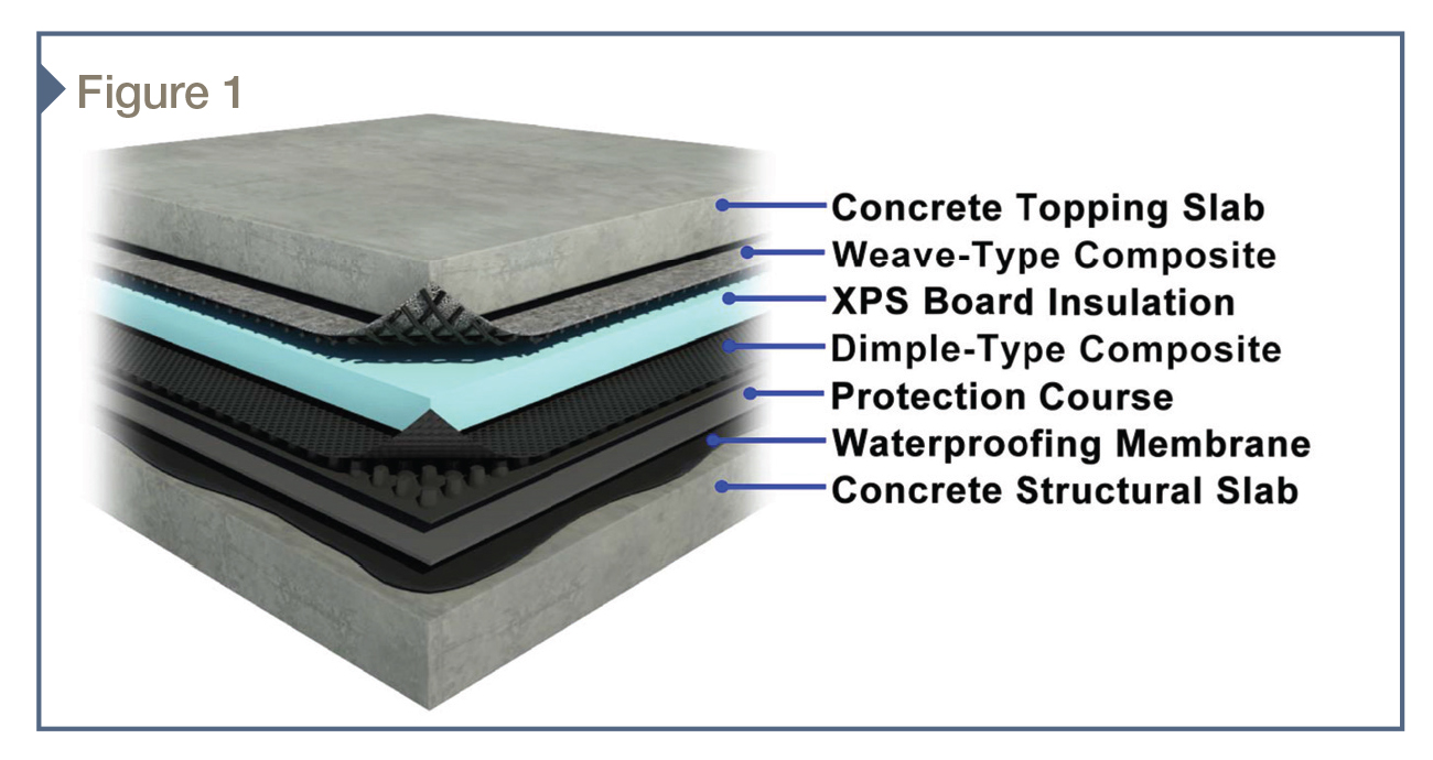
Figure 1 depicts some of the products frequently used in plaza construction. These include:
- extruded polystyrene (XPS) foam board insulation for thermal resistance or adjusting finished elevations;
- waterproofing membrane and protection course applied to an underlying concrete structural slab to keep water out of the occupied space below;
- composite drainage and air layers providing flow channels for water drainage; and
- hardscape paving materials such as concrete topping slabs and unitized pavers of brick, concrete, or stone.
There is a common misconception that plaza hardscape materials, whether monolithic (e.g. cast-in-place concrete) or modular (e.g. concrete, stone, or brick pavers), simply ‘sit’ on the underlying materials and do not ‘move.’ However, in reality, most supporting materials can compress somewhat. Loads applied at the hardscape surface are transmitted into the supporting materials, creating compressive stresses that in turn cause the material to locally shorten like a spring.
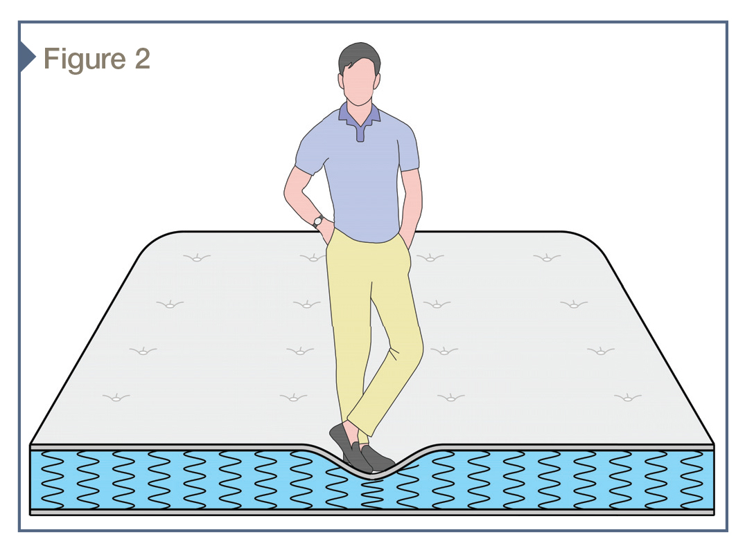
Anyone who has ever stood on a bed has encountered this phenomenon—feet sink down as the mattress springs compress, as shown in Figure 2. The heavier the person, the deeper his or her feet sink into the mattress since the springs compress more. In plaza hardscape construction, compressible materials that can behave like the springs in the mattress analogy include the XPS, waterproofing membrane, drainage mat, and protection course. Each of these materials can be defined by, among other things, a unique ‘springiness,’ more technically known as compressive stiffness.
Returning to the ‘standing on the bed’ analogy, the surface of the mattress that sinks down the most is directly under the feet, since those springs directly beneath are the ones carrying the person’s weight. Most of the mattress surface was unchanged, though, because the fabric enclosing the top of the mattress is flexible and cannot help spread the weight out onto other adjacent springs.
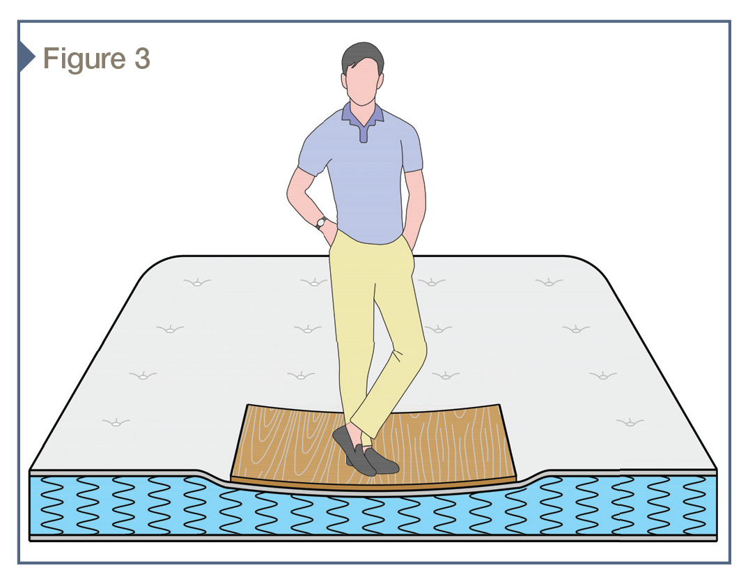
If this experiment was modified by first placing a sheet of 6.4-mm (1/4-in.) plywood on the bed, and then the subject stood on the plywood, the behavior would be changed. The mattress springs directly under the person’s feet would still be compressed the most, but some of the adjacent springs would also be compressed and the plywood would bend as it spread the load to the adjacent springs (Figure 3).
Depending on the weight of the person standing on the bed, the plywood might or might not crack due to the induced bending stresses. Cracking would depend on whether the bending stress exceeded the plywood’s flexural strength. In this case, the plywood is analogous to plaza hardscape materials such as concrete topping slabs and mortar setting beds for unitized pavers. The ability of a material to spread load out to supporting materials not directly under the load application point is related to flexural stiffness, which is, in turn, related to the material configuration, including thickness and the position, type, and size of any reinforcement present.
Multiple materials and manufacturers
The various components used below the hardscape surface of a plaza are in many cases manufactured by multiple entities, each with published product-specific properties. For example, XPS insulation types are described in ASTM C578, Standard Specification for Rigid, Cellular Polystyrene Thermal Insulation, which includes product requirements such as minimum compressive strength and density.
XPS insulation used in plaza construction includes, but is not limited to, Types VI, VII, and V, with minimum compressive strengths of 275, 415, and 690 kPa (40, 60, and 100 psi), respectively. The compressive strength is based on material uniformly loaded according to the procedure in ASTM D1621, Standard Test Method for Compressive Properties of Rigid Cellular Plastics. Similar to the XPS insulation, drainage composites will have a compressive strength value included on a manufacturer data sheet based upon uniform load testing according to the procedure in ASTM D1621. These compressive strength values represent individual material properties.
Compressive stiffness values for XPS insulation are also typically available through the manufacturer and, similar to the compressive strength, are based on uniform loading. Stiffness values are typically larger for higher compressive strength material (i.e. Type V XPS is stiffer than Type VI XPS) and decrease as the material thickness is increased (i.e. 25-mm [1-in.] thick XPS is stiffer than 50-mm [2-in.] thick material). Limited data is available on the stiffness of the other components previously described, including drainage/air composites, waterproofing membranes, and protection courses.
Designing for durability
The success or failure of a plaza hardscape installation hinges on many things, one of which is the durability of the finish materials. Cracking, spalling, and joint deterioration mar the plaza appearance and are generally considered unacceptable outcomes.
The authors have found hardscape/substrate interactions governed by compressive and flexural stiffness are often at the root of these types of problems. Avoiding them requires understanding the behavior of not only the individual component materials, but also the resultant assembly. The authors have found the industry literature lacking in this regard. To fill in some of the data gaps, the authors undertook a laboratory test program to evaluate representative plaza materials and assemblies for compressive strength and stiffness.
The authors tested hot-applied rubberized asphalt waterproofing membrane applied to concrete slabs, the membrane manufacturer’s approved protection course, weave-type and dimple-type drainage composites, and Type VII 50-mm (2-in.) XPS insulation board. Each material was subjected to compression testing, with load and deflections recorded using a computerized data acquisition system. Assemblies constructed from the tested materials were then subjected to the same tests, allowing material versus assembly behavior comparisons. Some of the resulting comparisons were quite surprising, with the measured strength and stiffness of the assemblies much lower than would be predicted by the individual material tests.
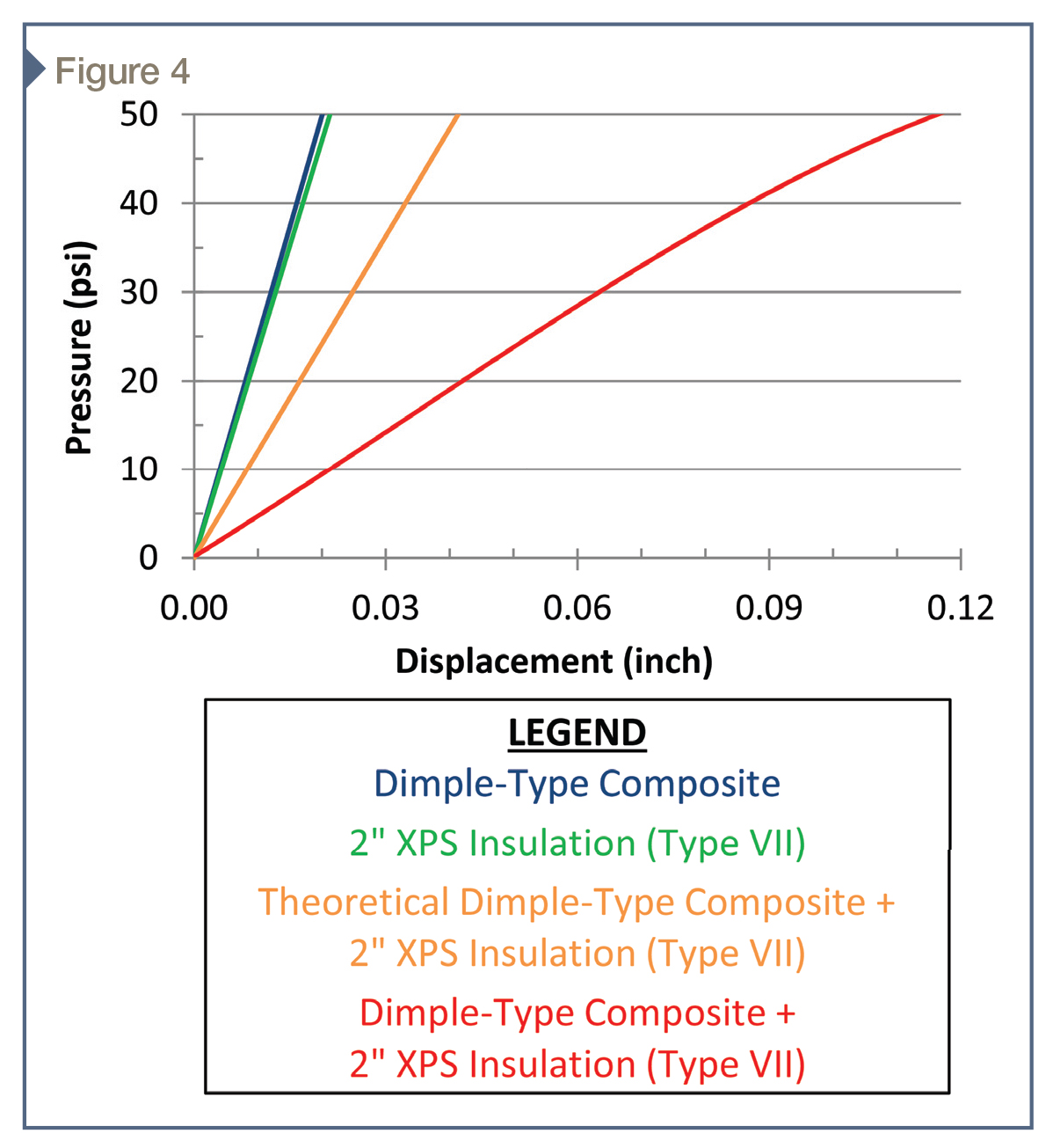
An example of compressive stiffness and strength reduction due to component interaction is demonstrated by tests performed on dimple-type drainage composite and Type VII 50-mm thick XPS insulation board. The following compressive stiffness values were determined for these components when loaded individually:
- 676 kPa/mm (2490 pounds per cubic inch [pci]) for the drainage layer; and
- 638 kPa/mm (2350 pci) for the XPS board.
These stiffness values represent a ratio of the uniform surface load in kPa to the vertical compression displacement in millimeters. Stacking the insulation and drainage layer, as would be expected in a plaza system, is similar to placing two springs end-to-end, assuming the load is distributed uniformly between components. The stiffness of these two components when stacked together as an assembly can be theoretically calculated to be 328 kPa/mm (1210 pci). However, testing performed on drainage composite and insulation assemblies resulted, on average, in a compressive stiffness of only 128 kPa/mm (470 pci)—a 61 percent reduction from the theoretical value.
The relationship between load and displacement for this test series is shown in Figure 4, where the slope of each line on the graph is equal to the compressive stiffness. The stiffness reduction between theoretical and tested is caused by partial contact between the insulation and drainage composite, resulting in increased localized stresses in the insulation. Testing of other assemblies confirmed this same concept applied at the interface between other plaza system components, such as drainage composites and waterproofing membrane with or without a protection course.
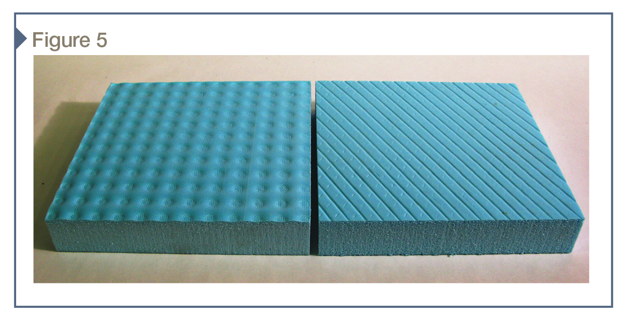
The tests also revealed localized crushing failure of the XPS board at load levels well below the advertised material compressive strength. The reduced contact area at the high points of the drainage mat change the behavior of the assembly from the uniform bearing condition assumed by ASTM D1621 to a series of smaller load points with open space in between—at least initially.
With increased load, the drainage mat high points pushed into the XPS until it conformed to the drainage mat surface undulations, as shown in Figure 5. Beyond the obvious effect on assembly compressive stiffness, crushing of insulation can result in a reduction of drainage/air composite capacity due to intrusion into the flow channels.
Assessing configurations
All the foregoing discussion about plaza component and assembly behavior under compression loading provides the background on which realistic design-phase assessment of proposed configurations can be performed. This is particularly important when heavy loads will be present either early (i.e. during construction and landscaping activities) or later (i.e. from planned vehicular traffic, maintenance equipment, or emergency response vehicles).
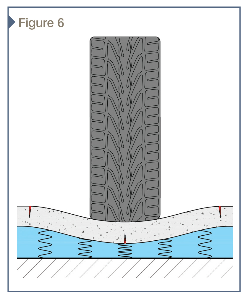
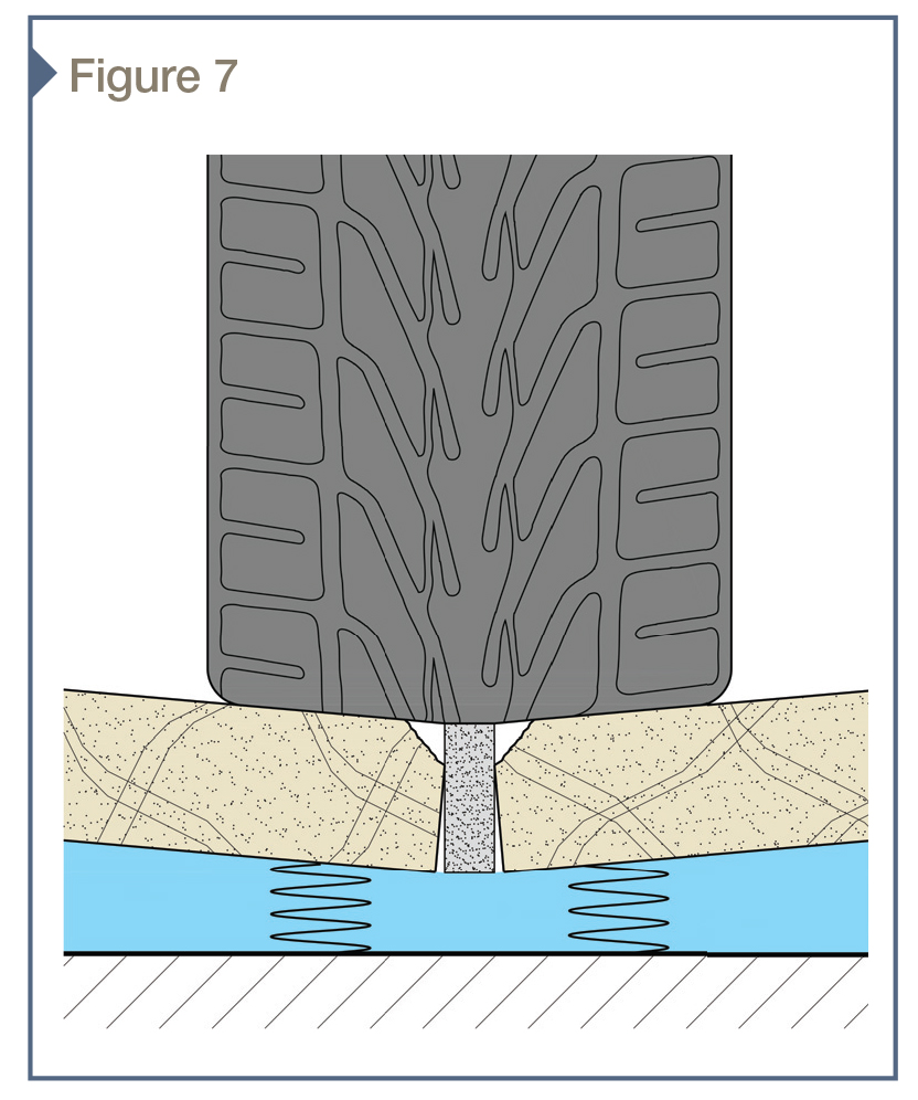
Overestimating the strength and stiffness of a plaza assembly can have serious consequences. Insufficient supporting material compressive stiffness can cause concrete topping slabs, pavers, and paver setting beds to crack due to larger than anticipated flexural stresses, as shown in Figure 6, and paver edge raveling and mortar joint crushing, as shown in Figure 7. These problems can be avoided by evaluating the entire plaza assembly, and not just focusing on the properties of individual components.
Flexural stress levels in concrete topping slabs, pavers, and paver setting beds that may be subjected to heavy loads should be evaluated taking into consideration not only the strength and stiffness characteristics of the hardscape materials to which the loads will be directly applied, but also those of the supporting materials. Without accurate component and assembly strength and load/deflection performance data available to incorporate into plaza design calculations, project-specific testing should be considered.
Designers can use the test results to evaluate the anticipated behavior of a proposed plaza design using analytical techniques such as finite element modeling to quantify anticipated displacements and associated stress levels. If unacceptable levels of cracking are analytically predicted, the design should be revised.
Possible design modifications include:
- Increase topping slab, mortar bed, and paver thickness when project constraints allow, thereby spreading surface loads over a wider area and increasing the flexural resistance. A trade-off exists with this approach in that the underlying structure, which may be a parking garage or the basement level of a building, may not be capable of supporting added dead load from thicker materials.
- Add reinforcement to topping slabs and mortar beds to control cracking. Care must be taken with this approach since reinforcement can control, but not eliminate, cracking.
- Modify component selections below the hardscape materials to increase the support stiffness, such as selecting a different insulation board material with a higher compressive stiffness.
- Consider adding bollards to preclude vehicular access to particularly problematic areas.
Conclusion
As is true with any design exercise, the key to avoiding plaza hardscape/substrate interaction problems is to be able to answer four key questions:
- What are the loads that are likely to be applied to the plaza?
- What path will the loads follow from the point of application to the underlying structural support?
- What materials will be incorporated into the design?
- What are the strength and load/deformation behaviors of the proposed hardscape and underlying support, drainage, and waterproofing materials?
Answering these questions will go a long way toward developing a successful plaza hardscape design.
Kurt R. Hoigard, PE, SECB, FASTM, specializes in evaluation and repair of distressed buildings and structures. Since joining Raths, Raths & Johnson in 1985, his experience has encompassed preconstruction consulting, implementation of construction-phase quality assurance programs, investigation of water leakage, deterioration and complete collapse, and repair design. Hoigard has received numerous awards from the American Institute of Steel Construction (AISC), International Masonry Institute (IMI), and ASTM International. His memberships include the American Architectural Manufacturers Association (AAMA), American Concrete Institute (ACI), International Code Council (ICC), and Structural Engineering Institute (SEI). Hoigard can be reached at krhoigard@rrj.com.
Brian T. Lammert, SE, PE, CDT, specializes in field investigation, lab and field testing, structural analysis, collapse investigation, peer review of new construction, and repair design and implementation. Since joining Raths, Raths & Johnson in 2005, he has directed load tests to evaluate distressed structures, component suitability for new construction, and failure causation. Lammert’s structural analysis experience includes development of computer models used for failure analysis, structural design peer review, existing structure evaluation, and repair design. He can be contacted via e-mail at btlammert@rrj.com.
Sign up for our weekly newsletter
Architectural materials and methods delivered right to your inbox
- CSI News and Notes: CSI Foundation’s construction camp; CSI spring exam; and more
- CSI News and Notes: CSI’s credentials; CSI conference theme; and more
- To be specific – CSI supports young AECO professionals
- CSI News and Notes: CSI’s foundation scholarships, national conference, and Crosswalk
- CSI News and Notes: AI’s impact; CSI 2024 conference, and more
Products


Read the Latest Issue