

Since the recommended bond-breaker materials are very thin and deformable over irregularities in the structural slab, the topping slab maintains intimate contact with the structural slab. This results in a uniformly supported topping slab on a non-yielding substrate. However, this is not the condition with split-slab installations because the waterproofing system is thicker and does not deform to the irregularities in the concrete substrate.
Waterproofing system thickness can range from approximately 13 to more than 25.4 mm (1/2 to more than 1 in.), depending on the type of protection and drainage layers employed. This is a significant difference that cannot be overlooked when the topping slab is specified for loading docks and other areas of heavy truck traffic, possibly resulting in the waterproofing being compressed and localized deflection of the topping slab. If significant consideration is not given to the topping slab design, the result can be flexural cracking.
Concrete topping slab design method
To arrive at a design method for a topping slab over waterproofing, a waterproofing system’s compressible layers must be evaluated and understood. In early 2000, engineering firm Simpson Gumpertz and Heger (SGH) investigated a cracked concrete topping slab at a large sports stadium in the western United States.
In a concourse subjected to heavy wheel loads from pallet jacks, the topping slab had been placed over waterproofing and a drainage layer. Based on the analysis and testing done during this investigation, the topping was shown to behave like a slab over a yielding substrate, rather than a uniformly supported slab on a non-yielding substrate. This behavior means the topping slab was subjected to bending stresses under high wheel loads. Therefore, an analogy can be drawn between the behavior of a topping slab over a waterproofing system and that of a concrete slab-on-grade over a compressible subgrade.
This analogy is key to the design of concrete topping slabs for split-slab waterproofing installations. With this knowledge, design professionals can follow published industry standards for concrete slabs-on-grade over compressible subgrades. When the topping slab is in a high-load traffic environment, one must also follow guidelines for vehicle loads on concrete slabs-on-grade. Well-established guidelines for evaluating the effect of vehicle loads for slabs-on-grade can be found in the aforementioned Concrete Floors on Ground. Following the analysis procedures in the PCA manual provides a slab thickness for a specific vehicle load, taking into account factors such as frequency of use, type of vehicle, and subgrade characteristics.
Additional design provisions include measures to address proper topping slab jointing and curing, as this minimizes cracking due to curled edges and corners and cracking caused by the concrete’s drying shrinkage. Curled edges and corners of a topping slab are particularly vulnerable in a high-load traffic environment because heavy-wheeled loads on an upturned edge or corner subjects the concrete to flexural stress that could result in cracking. To minimize curling, spacing and detailing of the control and construction joints should be carefully considered, as well as concrete placement and curing procedures. These design provisions can also help reduce random cracking caused by the concrete’s drying shrinkage.
As concrete shrinkage occurs when water from the concrete mix leaves during curing (i.e. a reduction in concrete volume), additional consideration should be given to using a low shrinkage concrete mix and a shrinkage-reducing admixture (SRA).
None of these industry-standard recommendations for jointing and curing of concrete topping slabs are new or unique for a concrete slab-on-grade design; they can be found in PCA’s Concrete Floors on Ground and in ACI 302.1R. Nevertheless, they are listed in this article because they are important design provisions critical for a high-performing concrete topping slab over waterproofing in a high-load traffic environment.
Case study
The design method presented in this article is the outcome of analysis, testing, and experience gained during investigations of failed concrete topping slabs and slabs-on-grade. While there is no accepted industry standard or established testing to support the method, it was used on a topping slab design that has performed well for eight years in an interior loading dock project for a large medical campus in downtown Los Angeles (Figure 1).
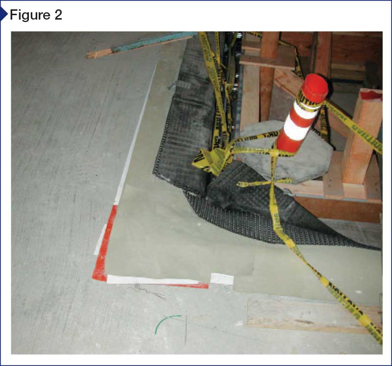
The waterproofing system consists of a felt leveling layer placed over the structural slab with a loose-laid thermoplastic waterproofing sheet, oil containment sheet, and protection layer over the felt. Over these layers is a prefabricated composite drainage panel, comprising a three-dimensional high-strength and impact-resistant polypropylene core with a woven geotextile fabric bonded to the top side (Figure 2).
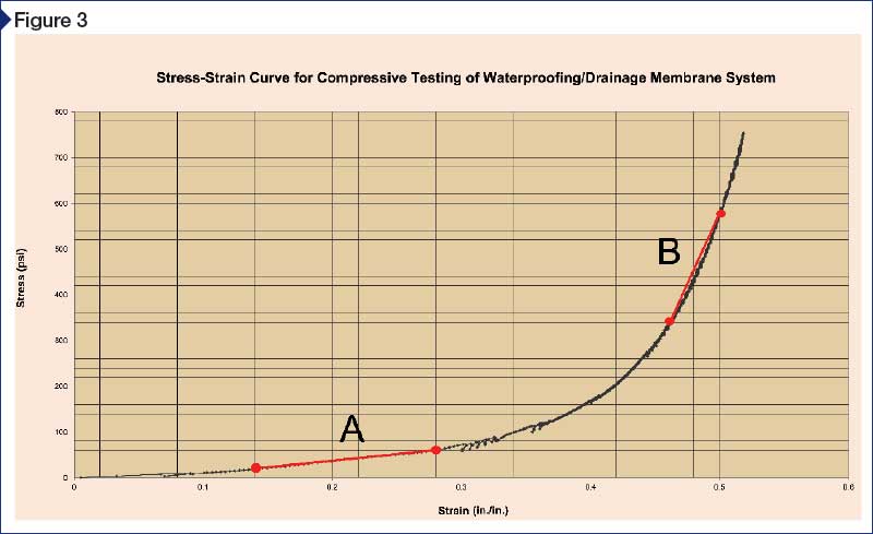
The first step to design a topping slab over a compressible subgrade is to obtain data on the waterproofing’s load/deformation properties. Since there is little to no data available for these systems, samples were load-tested to determine the deformation characteristics. The result is the graph in Figure 3, which has two relatively straight segments—Segment A at the lower end and Segment B at the upper—and a curvilinear transition between them.

