3D modeling used to create complex IMP feature on Maryland college
Photos courtesy Kingspan
by Joshua Morland
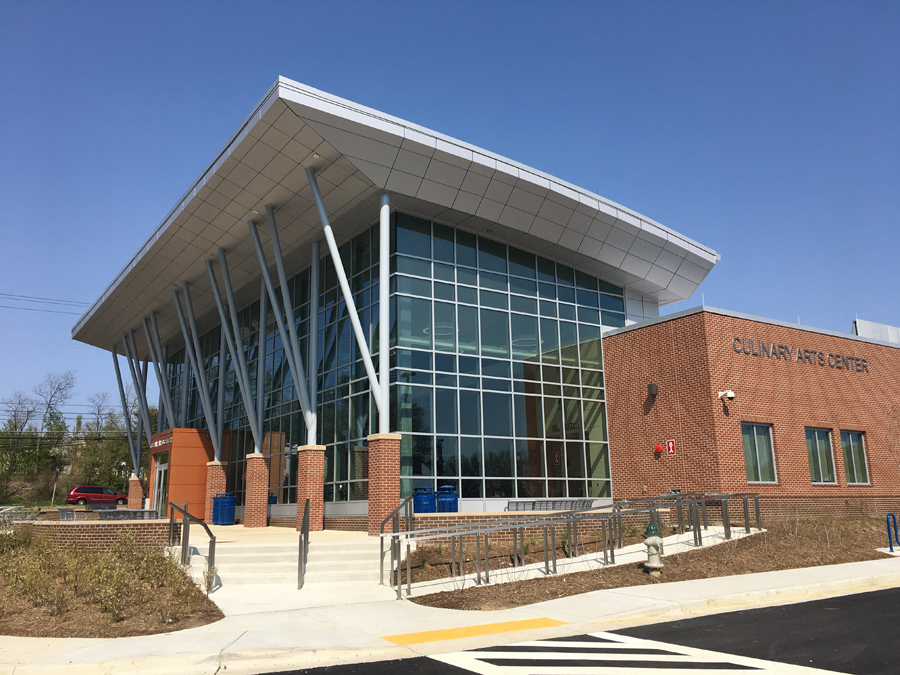
Prince George’s Community College in Largo, Maryland, is serving up culinary arts classes in a new 1979-m2 (21,300-sf) building designed by Grimm+Parker Architects.
A signature element of the new building is a high canopy over the building’s main entrance, which is a large glass atrium. The canopy is created out of insulated metal panels (IMP). It presented a challenge for the IMP manufacturer, as it not only is a sweeping curve, but also has sloped soffits. This added a degree of difficulty in engineering the layout, as all the panels used in the project are flat. Using curved panels would have driven the cost up significantly.
The canopy design utilizes segmented curves, which created a challenge in attaching flat panels to a curved surface; in this case, metal panels attached to metal stud framing with plywood sheathing on top of curved I-beams. The panels were segmented so they could be tilted as a four-panel assembly along the curve. The top panel has a 127-degree longitudinal bend. The middle panel is flat, the bottom panel has a 143-degree longitudinal bend, and the soffit is flat. There is a light gauge framing on the sloped portion of the soffit with a dimension of 1473-mm (58 in.) between the upper and lower bent panels that needed to be consistent along the whole curve so the panels would fit properly and not change in width. Since the framing and the bend angles were consistent along the curve, and the radius was not too tight, it allowed for the segmenting of the panels. The larger the radius, the longer the flat panels can be without becoming unstable or unattachable. On this project, the panels were slightly beveled on the ends so the vertical joint between the panels remained perpendicular to the ground and did not slope at an angle. This was important because the architect specified the vertical joints needed to align with the mullions on the atrium.
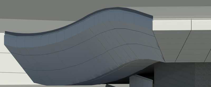
Grimm+Parker used building information modeling (BIM) for their design of the project. The IMP manufacturer had to choose between 2D and 3D to create a design that was acceptable and feasible for the canopy. Both drafting processes will achieve the desired result, but the manufacturer opted for 3D due to the complexity of this project.
Working in 3D allows the designer to have an in-depth look at how the materials—insulated metal panels in this case—will fit around the curves and edges of a project.
On the architectural side, BIM calculates the quantity and size of doors, windows, faucets, and other building materials relevant to architects. There is a similar benefit on the engineering side. For the culinary arts center, the IMP design team set up a series of “families,” a term they use for panels, flashing, extrusions, and other materials to be employed in an assembly modeled in 3D. Once these parametric families are created, they can be inserted into a project and placed on virtual walls just like installing the panels in the real world. When the design is complete, the software automatically generates a spreadsheet detailing the number of panels and fasteners, square footage, length of extrusion, and other materials necessary to complete the installation. This is faster and more accurate than the traditional method of adding all this information by hand.
In 2D design, once the project is drawn and approved, the designer has to then go back and determine dimensions for the panels and the materials needed to create the bill of materials (BOM). It also comes with the increased risk of human error. Since the BOM is not generated automatically like it is when using BIM, a simple typo can create a disaster. It would not be unusual for a mistake like that to cost tens of thousands of dollars to correct if it puts a jobsite on hold and delays a project.
In some cases, BIM allows all the trades involved in a project to each model their portion of the project and combine them all onto one model. This creates a high level of coordination. Conflicts can be discovered and corrected well before construction begins.
Designing and engineering in a virtual 3D environment can lead to a more efficient and accurate final project in the field, as well as substantially decreasing the lead time of receiving materials on large, complicated projects. In the case of Prince George’s Community College, the architect and IMP manufacturer utilized BIM to create the best recipe to design and utilize IMPs in the new culinary arts center.
 Joshua Morland is a drafter at BENCHMARK by Kingspan. He can be reached at joshua.morland@kingspan.com.
Sign up for our weekly newsletter
Architectural materials and methods delivered right to your inbox
- CSI News & Notes: CSI’s impact earns official recognition; celebrate leaders, mentors, and innovators; and more
- CSI News and Notes: CSI spring certification exams open; scholarships available; and more
- CSI News & Notes: CSI MSR heading to San Diego; spring certification exams open; and more
- To Be Specific: Why CDT Should Be Your First Move
- CSI News & Notes: CSI Fellows share member benefits; and a New Year’s Resolution to keep
Related Products

Read the Latest Issue