Verifying the Details: Ensuring quality during glazing installation to avoid costly repairs
by Katie Daniel | February 2, 2018 9:25 am
 [1]
[1]by Cynthia L. Staats, PE, LEED AP, and Michael J. Louis, PE
Nothing gives construction teams heartburn faster than leaks in a newly installed curtain wall or storefront assembly. With the growing desire for glass-clad buildings and shorter construction schedules, there is a rise in easily avoidable leaks in glazing systems due to installation omissions and shortcuts. Although some leaks can be easily remedied, others are systemic and can be persistent for the life of the glazing system.
The details outlined in this article are some of the more consistently overlooked items during a glazing system’s installation. It is a good practice to discuss these items with the construction manager (or general contractor) and the installer at the beginning of the glazing system installation. While the shop drawing and submittal process may be intended to cover some of these items, the individual who usually develops and submits the shop drawings is not always the person who installs the glazing system.
This article explores stick-built and field-glazed installations, but much of the information can also be useful when inspecting some aspects of a unitized wall assembly at a fabrication shop. Correcting these deficiencies after the installation is complete can be costly both in terms of money and schedule.
Starting with the sill receptor
The last line of defense for directing incidental leakage back out of the glazing system, the sill receptor goes by several names, including sub sill, starter sill, and receiver. During the system’s installation, there are two important aspects to ensure—the sill receptor is appropriately sized for the glazing system and its splices are properly detailed. (While the installer is ultimately responsible for this aspect of the job, projects do not always play out in the way they are supposed. It is beneficial for the whole project team to be aware of these issues, but each person has his or her own role with which they are usually preoccupied. The last line of defense would be the building envelope engineer—it would be helpful for the building envelope engineer to bring this to the project team’s attention during construction administration site visits. However, the contractor is ultimately responsible to ensure this.)
 [2]
[2]Photos courtesy Simpson Gumpertz & Heger
A sill receptor is made out of a two-dimensional extrusion; its main function is to provide a means for anchoring the sill of the glazing system product. As a secondary function, the sill receptor is intended to function as a ‘pseudo-flashing,’ containing and draining the infiltrating water back to the exterior. To suit this latter function, the sill receptor must be fitted with end dams so the infiltrating water does not simply flow off the ends of the sill receptor and leak to the building interior.
To create the end dams, flat stock aluminum is fastened to each end of the sill receptor extrusion, and sealant is applied where the flat stock contacts the extrusion to create three-sided containment. We have often observed the installer cutting the sill receptor to the same length as the glazing system frame and then forcing the glazing system onto the sill receptor (which ends up too snug). This results in end dams being forced outward and the sealant between the end dams and the sill receptor tearing apart. The same outcome can also occur when the installer is not careful in inserting the glazing system onto the sill receptor or if the installer omits the fastener securing the end dams on the sill receptor.
It is very difficult to achieve a reliable seal between the sill receptor and the end dam after the glazing system is installed. If the end dam seal is disrupted during installation, the best practice is to go back and create a continuous seal before proceeding with the installation.
Likewise, the splice between two sill receptor extrusions is another critical seal that cannot be reliably sealed after the glazing system is installed. The splice is typically made by bedding an L-shaped piece of aluminum or silicone membrane in sealant at the joint. Therefore, the installer can only access the upturned leg portion of the sill receptor after the glazing system is installed. The horizontal portion of the extrusion cannot be accessed after the glazing system is installed. If this seal is omitted during installation or not properly formed, water collected by the sill receptor can leak into the building.
 [3]
[3]Frame seals
Frame seals are the seals between two mullions joining together. They are best applied in two steps:
- Sealant should be applied to the surfaces contacting each other. The amount of bond surface is limited by the thickness of the extrusion.
- After the two members are fastened together, additional sealant should be tooled over the face of the two members coming in contact.
Once the glass is in place, frame seals cannot be reliably installed. Verifying the frame seals are in place before the glazing is installed will prevent a lot of headaches.
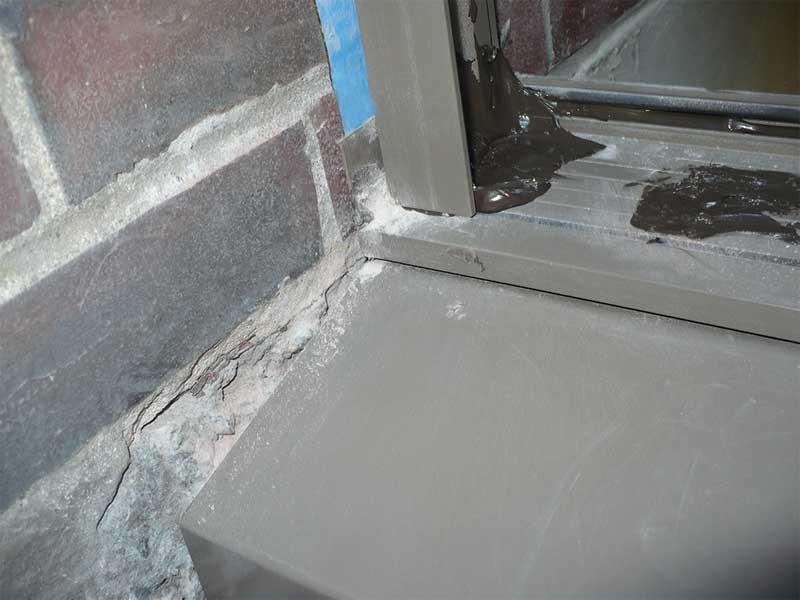
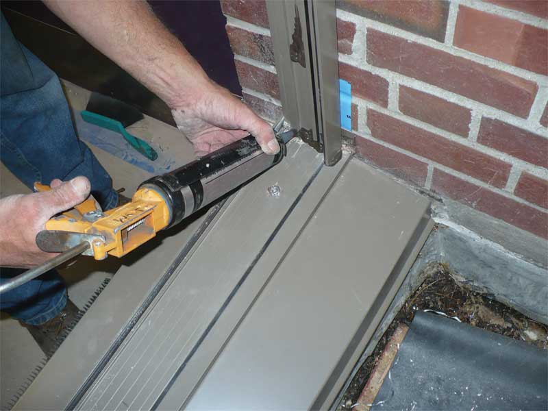
Cleaning before sealing
Substrates need to be clean and free of moisture, oils, dirt, and debris before applying sealants. Countless times, we have witnessed an installer in the field apply a big dollop of sealant over metal shavings, stone or brick dust, and/or sawdust from drilling pilot holes. Moisture, oils, and debris contaminate the sealant bond surface, making it difficult to achieve continuous adhesion.
Since the integrity of the seals within a glazing system are critical to the system’s performance, incorporating debris within the sealant is counterproductive to that end goal. Also, the majority of these seals cannot be accessed once the glazing is installed.
Extrusion orientation
The shape of the extrusion can be used to direct water back out of the system. These extrusions have an intended orientation. We investigated a glazing installation where the contractor submitted shop drawings showing the correct orientation of an intermediate horizontal. The shape of the extrusion when installed with the correct orientation required the contractor to install the glazing from the exterior. Since the contractor did not want to install the glazing from the exterior, he instead flipped the intermediate mullion to allow for the system to be glazed from the interior.
This seemingly small deviation from the shop drawings resulted in water being directed to the interior instead of being drained back out of the system. The contractor offered to add additional seals, but these would not yield the same service life or performance as a properly oriented extrusion. For this reason, it is very important to verify proper orientation of the members during installation.
 [4]
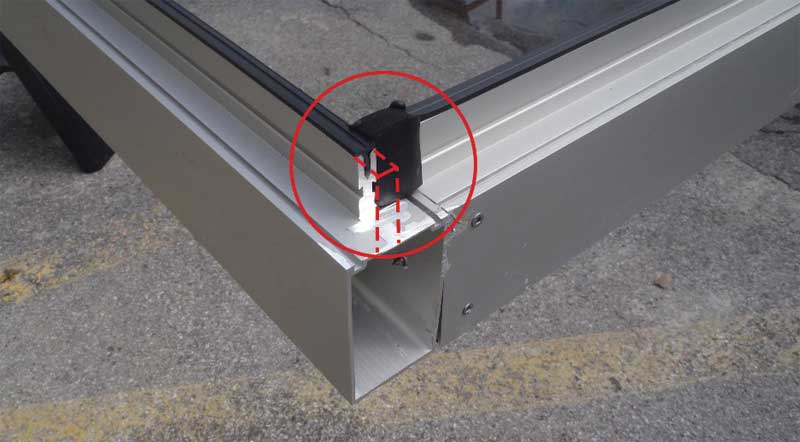
[4]Reliable perimeter weatherseals
Installation instructions often show a bead of sealant as the perimeter weatherseal. With the section cut through the axis of the extrusion, all appears to be well. However, at the top and bottom of the vertical extrusions, the bond area for the perimeter weatherseal is reduced to the thickness of the extrusion.
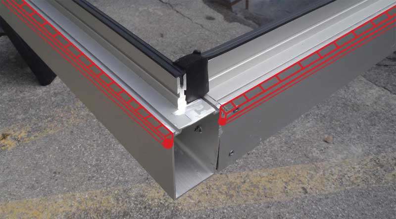
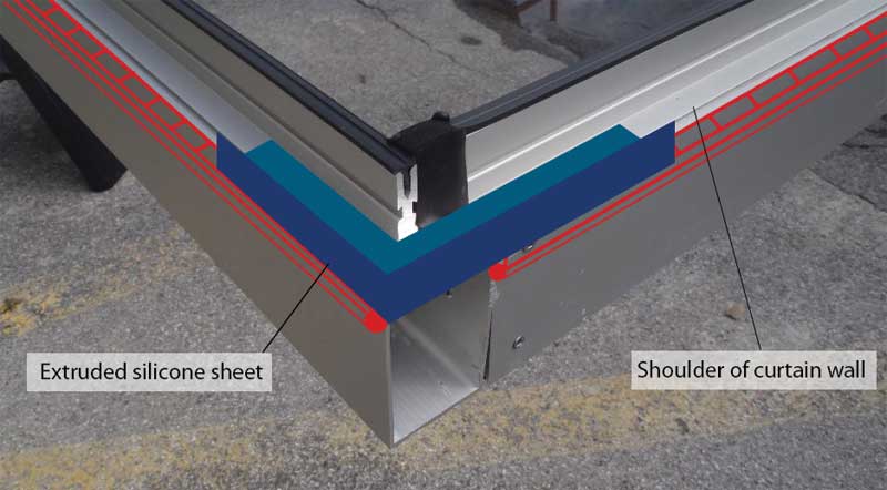
The sealant joint needs to be adequately bonded to its substrate to perform and flex as intended. Virtually all sealant manufacturers agree less than 6.4 mm (¼ in.) of bond area is insufficient for maintaining a reliable weatherseal. The reduction in bond surface is an inherent weakness in the perimeter weatherseal. This issue is further complicated by the stem or neck of the vertical extrusion. During the design phase, we often recommend the perimeter weatherseal be made with a silicone tape. This ‘transition membrane’ is applied to the face of the mullion, often referred to as the shoulder. The vertical mullion stem needs to be coped to allow for the transition membrane to extend onto the face and create a reliable corner detail.
A value engineering phase often eliminates the transition membrane along with the stem coping and the perimeter weatherseals are back to being sealant. This is not a prudent design decision. If a leak is discovered after installation, it becomes increasingly difficult and costly to cope the stems of the vertical mullions and install isolated transition membranes at the vertical mullions after the glazing system has been installed.
 [5]
[5]Allowing for slab deflection
A glazing system is not designed for, or intended to bear, the load of a floor slab above. The contractor is responsible for taking field measurements to replace the measurements provided in the design drawings. In several instances, we have seen glazing systems that do not allow for slab deflection despite having shop drawings to the contrary.
Often, the unit being installed is too large and does not allow for slab deflection. More likely, however, the units were based on a fixed dimension on paper and the building was not constructed to those dimensions or the notion of building tolerances were not taken into consideration. In these cases, to avoid placing the glazing system in a potentially hazardous condition, either the structure or the glazing system needs to be modified. Since modifying building structural elements is not cost-feasible, modifying the glazing system is generally the least disruptive approach to pursue. However, modifying a system in the field does not come without substantial cost to the installer. Many litigation proceedings play out in this fashion to no one’s benefit.
 [6]
[6]Joint plugs
Joint plugs are rubber or plastic components filling the gap between horizontal and vertical mullions in a curtain wall or storefront system. Not all curtain walls and storefronts have joint plugs, but some of these systems are designed to allow water to move vertically within the vertical mullions and drain out at the bottom of the system. Where joint plugs are used, they are an essential component in the water management capabilities of the higher-performing glazing systems. Omitting joint plugs can seem like a benign offense, but the joint plugs serve three critically important roles.
1. The joint plug helps compartmentalize drainage channels so incidental leakage can be promptly directed back out of the glazing system.
2. Joint plugs stop water from draining onto the tops of insulated glazing units (IGUs) below. Glazing systems that do not include joint plugs in their design deal with this issue with an accessory called a deflector—this allows water at a horizontal mullion to drain down the vertical mullions without tracking back to the top of the IGU below. Water allowed to collect on the seals of IGUs will deteriorate them, causing premature failure or fogging of the glass.
3. Joint plugs help seal the gap between the horizontal and vertical mullions.
Inspecting joint plugs is an important task whether performed in the field or at the fabrication shop. Inspection can be messy as the joint plugs should be covered with sealant at all contact surfaces with the horizontal and vertical mullions, but also built up with sealant along the top of the plug to form a shed to move water toward the weep holes on the horizontal mullion.
Using a dulled dental instrument, the interface of the joint plug with the horizontal mullion can be probed to verify the sealing continuity; one should also see sealant filling the raceway for the pressure bar fasteners and extending 25 mm (1 in.) or more away from the joint plug.
The sloped sealant bed atop the joint plug should not contact the edges of the IGU as this will prevent the free flow of water to the weep holes around the edges of the glass.
Anti-walk blocks
Anti-walk blocks keep a glazing unit from shifting or walking from either side in the glazing pocket. These rubber blocks are slid in at the sides of the glazing pocket next to the glass and they help to prevent glass-to-metal contact, which can cause glass breakage.
We rarely see anti-walk blocks being installed, but these components are nonetheless beneficial in all glazing systems. Anti-walk blocks are essential in glazing systems with unequal glazing pocket depths as may occur in pocket glazed storefront assemblies. We have seen glass move into the deep pocket side of a pocket glazed glazing system (caused by wind vibration) to the point where several IGUs lost their complete bite along one side of the unit. Anti-walk blocks are an inexpensive component of a glazing system that can prevent these costly issues.
Conclusion
Although the shop drawing and submittal phase is intended to serve as a means for establishing a plan for quality control, they cannot depict all of the nuances outlined in this article. Being onsite during the initial installation is truly paramount to the end performance of the glazing system, as it can help to set the stage for workmanship expectations that are not captured in the shop drawings or the manufacturer’s fabrication and installation instructions.
As mentioned, the person preparing the shop drawings is typically not the same person who installs the glazing system—more often than not, pertinent details get overlooked or misinterpreted. An honest mistake or seemingly small oversight can become a costly regret. In addition to the cost of addressing these issues, fixing them can—and often will—have an impact on the schedule and someone’s pocketbook.
Cynthia L. Staats, PE, LEED AP, is senior staff II in Simpson Gumpertz & Heger’s (SGH’s) Building Technology group, where she has worked for 10 years. Staats works on projects involving waterproofing investigation and design of building enclosure systems, including plazas, exterior wall systems, windows, roofing, foundations waterproofing, and stone cleaning. She is a member of the ASTM D18 Committee on Soil and Rock. Staats can be reached via e-mail at cstaats@sgh.com[7].
Michael J. Louis, PE, is a senior principal with SGH, specializing in the design, construction, and performance of building enclosure systems. He focuses on glass-and-metal fenestration systems, but also has extensive experience with below-grade and terrace waterproofing, exterior walls, and flat, steep, and low-slope roofing. Louis brings a solid understanding of materials, interaction among these materials and with other building systems, and the integration of waterproofing, structural, and energy systems to achieve optimal building performance. He is a member of ASTM C24 Committee on Building Seals and Sealants, American Architectural Manufacturers Association (AAMA), Building Enclosure Council (BEC), and American Society of Civil Engineers (ASCE). Louis can be reached via e-mail at mjlouis@sgh.com[8].
- [Image]: https://www.constructionspecifier.com/wp-content/uploads/2018/01/140193_00_POIN_N65.jpg
- [Image]: https://www.constructionspecifier.com/wp-content/uploads/2018/02/Photo-2-Cleaning-Before-Seal.jpg
- [Image]: https://www.constructionspecifier.com/wp-content/uploads/2018/02/Photo-3-Words.jpg
- [Image]: https://www.constructionspecifier.com/wp-content/uploads/2018/02/Photo-4.jpg
- [Image]: https://www.constructionspecifier.com/wp-content/uploads/2018/02/Photo-5-Words.jpg
- [Image]: https://www.constructionspecifier.com/wp-content/uploads/2018/02/Photo-1-Cleaning-Before-Seal.jpg
- cstaats@sgh.com: mailto:cstaats@sgh.com
- mjlouis@sgh.com: mailto:mjlouis@sgh.com
Source URL: https://www.constructionspecifier.com/53465-2/