

by John H. Koester
Three decades ago, this author was issued his first patent; it was for a weep system. The main ‘claim’ was the forming of a mortar bed joint’s bottom side to create tunnels or channels into the cores or cavities of masonry walls. In the process of researching information for the patent’s content, something became very apparent—many of the industry-standard accepted practices for weeping had little to no scientific basis.
The spacing of weeps 406, 813, 1219 mm (16, 32, or 48 in.) on center (oc) is one example of a common practice without scientific support given moisture management and modular spacing patterns have little correlation. While there may be rules calling for certain spacing (i.e. 2006 International Building Code [IBC] 2104.1.8?Weep Holes), that does not mean there is supporting research.1 Some things are just done long enough they become standard practice.
With the old weep technology and its spacing, water indeed got out of the cavities and cores of masonry walls. However, it was not necessarily all the water, always through the weeps, or a fast process. Moisture management in masonry walls is about getting the water away from, off of, and out of the construction detail as quickly as possible. The length of time moisture remains is in direct proportion to the amount absorbed into the materials.
What is a weep?
In the first volume of its Masonry Training Series (1996), the Mason Contractors Association of America (MCAA) defined weeps as “openings placed in mortar joints of facing material at the level of flashing, to permit the escape of moisture.” In other words, they allow the exit of any liquid water that drained down to the top surface of a flashing from the masonry wall’s core or cavity.
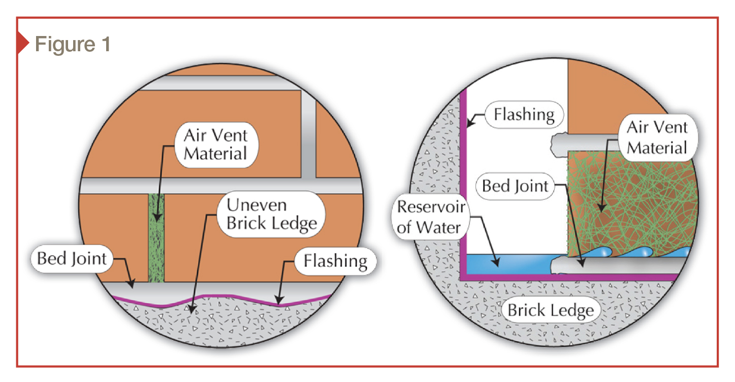
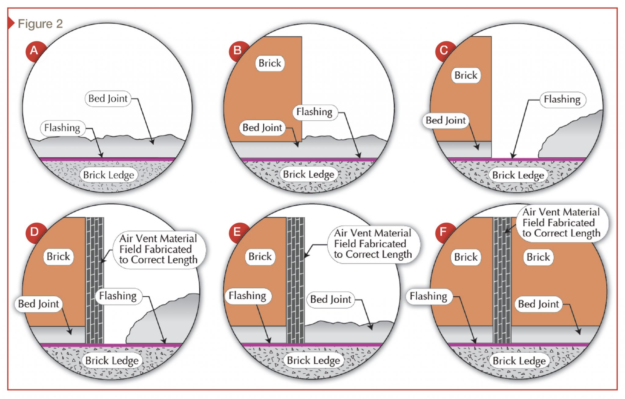
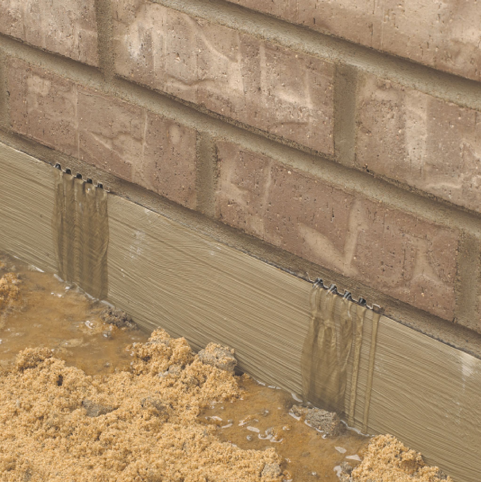
Some have incorrectly adopted use of head joint air vent material and devices as weeps. Many of these air vent devices are not the proper dimensions to accommodate potential variations of a first-course bed joint of mortar and masonry unit. The non-voided portion of the bed joint of mortar becomes a dam that causes water to form a reservoir at the bottom of the cavity (Figure 1). Further, installation of this type of material—even when field-fabricated to the right height—is labor-intensive and a cumbersome, multistep process (Figure 2).
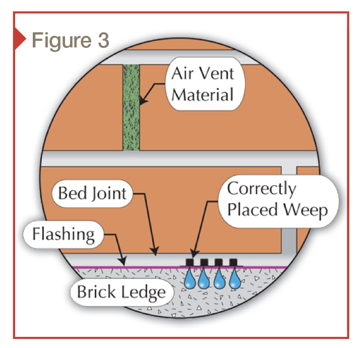
The appropriate detail for a masonry air vent and a masonry weep would look like Figure 3. The weep holes are at the lowest point of the masonry wall (and cavity) and are spaced 267 mm (10.5 in.) apart to improve the mathematical chances one of them will be at the lowest point of the masonry wall (and cavity) where the water is. (The bottom side of the bed joint of mortar is not part of the modular layout of the wall; therefore, the forming of the bottom side of the bed joint of mortar to create a weep system is also separate from any modular considerations.) The masonry wall air vents should be spaced every third brick head joint, one to two courses above the bottom of the cavity, and above the weeps. They should also be a course below the top of the vertical height of the flashing mechanically fastened to the backup wall.
This detail provides excellent weeping capacity and potential air intake to improve airflow in the masonry wall’s cavity. The positive outcomes include improved chances for pressure equalization of the cavity with the pressure on the masonry wall’s exterior surface. This may move moisture-laden air (i.e. water vapor) deeper into the exterior building envelope due to the the scientific principle of high to low pressure equalization. Additionally, providing equal air intakes and air exits at the wall’s top and bottom improves airflow in the core or cavity. This will have some positive impact on the masonry wall’s ability to dry out.2
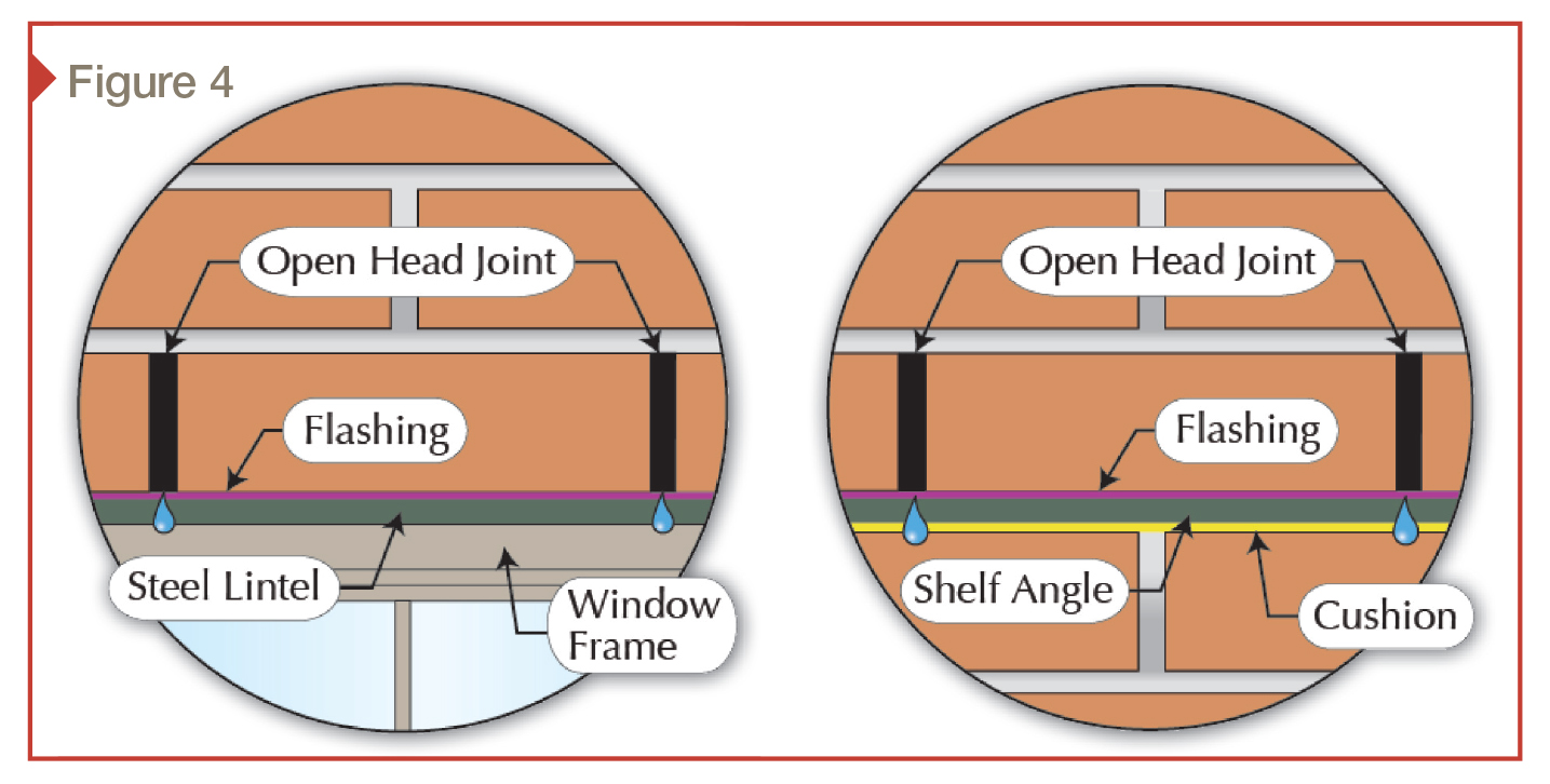
Commonly used on lintels and shelf angles, open-head joints have the potential to provide both weeping capacity and airflow (Figure 4). They also eliminate problems with the related bed joint of mortar because the first brick course is usually laid dry on the flashing material covering the lintel or shelf angle that waterproofs the bottom of the cavity.
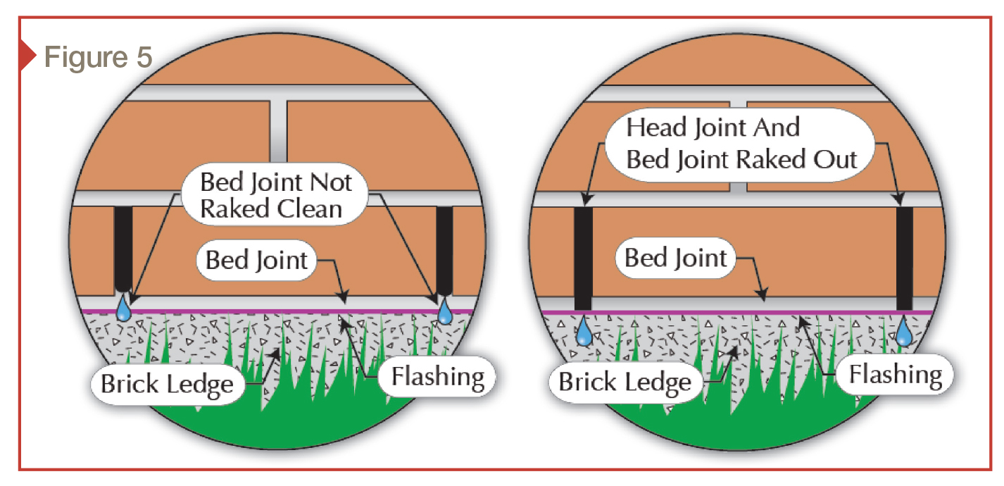
When employed with a bed joint of mortar, there is a chance the bed joint directly below the open head joint will not be raked clean of mortar. If this occurs, water flow out of the detail is dammed up. In other cases, the bed joint of mortar is left in place because raking it out is not architecturally appealing as it breaks the coursing lines of the bed joint (Figure 5).
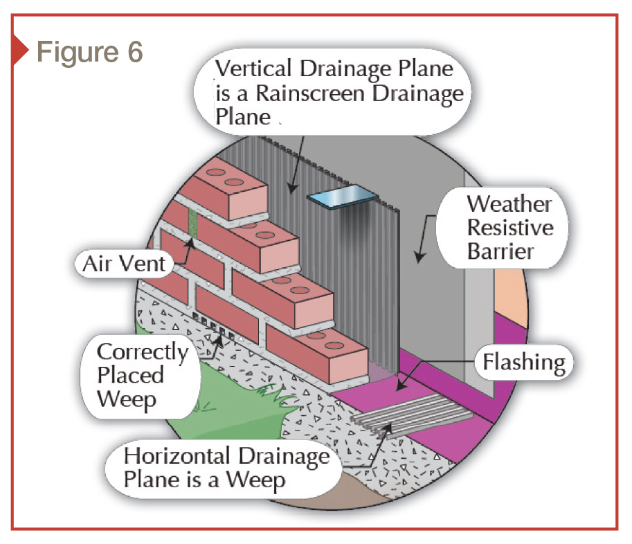
It is critically important the cavity or core (the void behind the veneer) is open and clear of obstruction to allow liquid water to move from a high point of entry to the lowest point of the cavity or core, which is the top surface of the flashing. In the past, attempts to produce this part of a masonry veneer wall have been the responsibility of masons. The results have varied from good, open, clean cavities to those bordering on being poured solid. Predictable, high-quality results are required to effectively manage moisture. The introduction of rainscreen drainage planes to maintain this void has improved the required predictability (Figure 6).
Detailing the solution: a case study
Proper moisture management for masonry assemblies involves more than just knowledge of weeps. In devising the best approach, dividing the envelope into ‘risk zones’ is crucial. These ‘separations’ are determined by factors such as the building site and climate, the structure itself (i.e. multistory versus low and sprawling), and the materials specified for the envelope. Ranging in intensity from very low to extremely high, the zones are specific sections of the exterior building with unique exposures to moisture. There are many examples of premature failure of the exterior building envelope illustrating entrapped moisture has migrated from one location (zone) to another. This migration, along with the costs associated with premature failure, can be prevented with the appropriate detailing.
The process of determining moisture management zones begins at any part of the exterior envelope. In most cases, since moisture moves from a high point of entry to a low point in the exterior building envelope, starting at the top makes sense.3
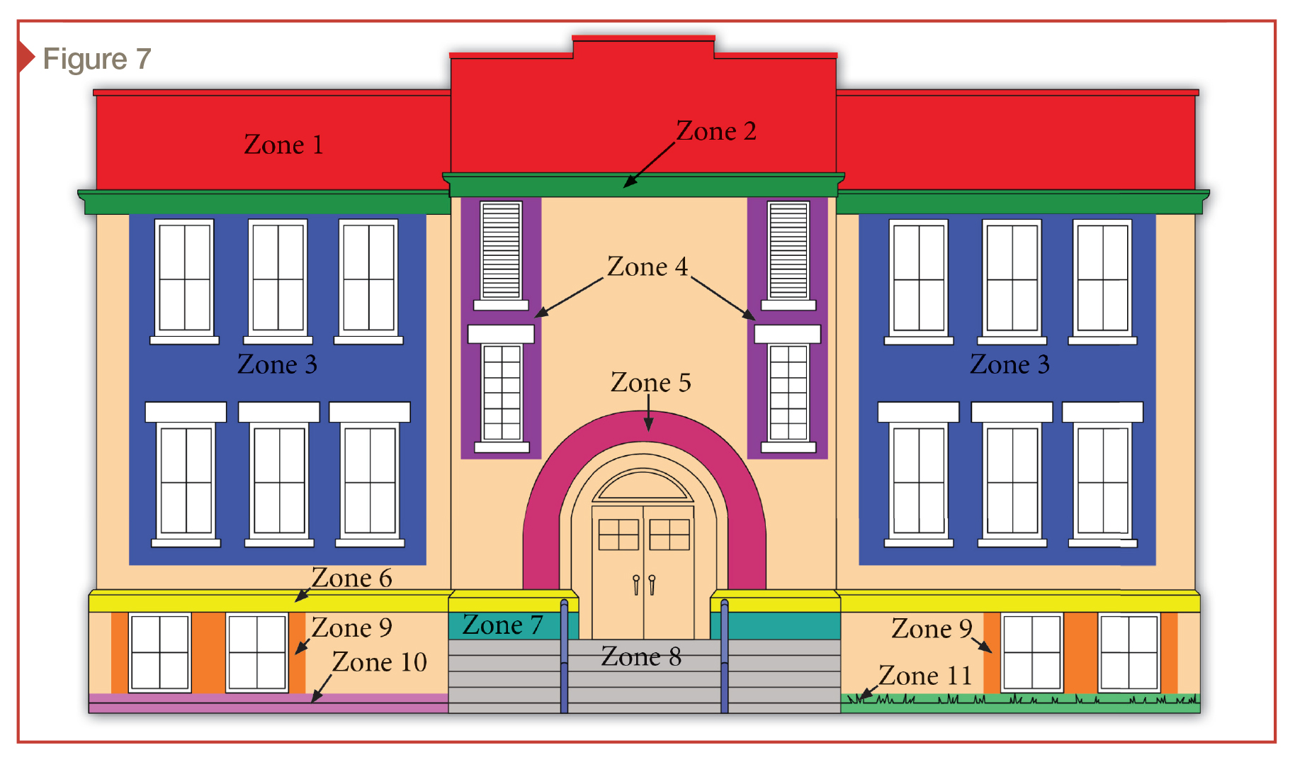
In some cases, the process is two steps: first, a determination of a ‘general’ risk zone, followed by a second determination of ‘associated zones’ within (e.g. parapet walls and window openings). Figure 7 is an example of assessing moisture management risk zones for the purpose of designing the appropriate flashing and weep detail to help modify the moisture management risk. They include:
- parapet wall (Zone 1);
- decorative cornice belt (Zone 2);
- window openings (Zone 3);
- louver openings (Zone 4);
- door openings (Zone 5);
- intersection of non-frost-affected concrete stoop and masonry wall (Zone 7);
- intersection at grade of masonry wall and frost affected sidewalk (Zone 10); and
- intersection at grade of a masonry wall and landscaping (Zone 11).
Parapet
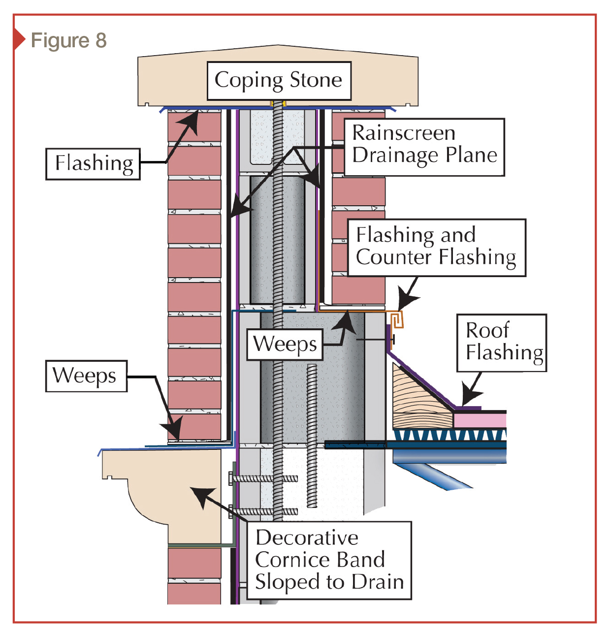
Zone 1 (Figure 8,) is an example of a parapet wall with multiple associated moisture management details:
- coping;
- roof flashing and counter flashing; and
- transition point from bottom of parapet wall to top of exterior building envelope that encloses the interior spaces—the ‘decorative stone cornice band.’
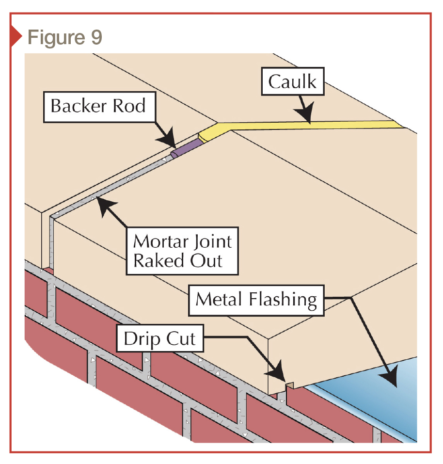
The coping on the parapet wall is the roof of the parapet and must be waterproofed (Figure 9). One of numerous exterior building envelope details with many responsibilities, coping stones are frequently positioned out of sight. The intersection of the roof and bottom back side of the parapet is another moisture management detail with numerous roles. The roof flashing and the parapet wall counter flashing must be designed to be both waterproof and movement-absorbing; they must be able to accommodate expansion and contraction of the roof assembly.
Decorative cornice
The point where the bottom of the parapet wall ends, and the top of the exterior building envelope enclosing the interior begins, is sometimes unclear. Zone 2 is the top of the decorative stone cornice band (Figure 10). One should not be misled by the term ‘decorative;’ it is also a moisture-diverting detail and a ‘roof’ for the wall and windows below it.
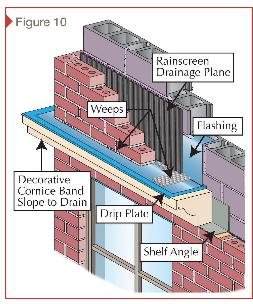
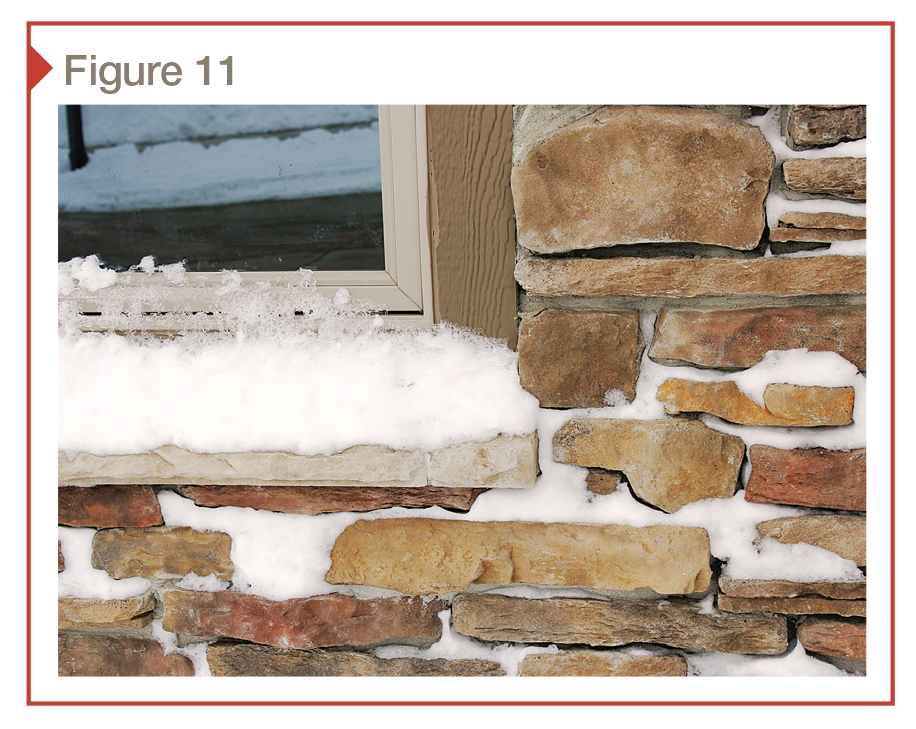
There is a misconception patterns on the exterior of the building envelope veneers (e.g. stucco, wood, brick, or stone) are simply decorative. In truth, their primary function is protection. They direct moisture away from sensitive details, such as windows and doors. In the past, the construction industry understood this multipurpose concept and had the sense to make them both functional and aesthetically appealing. The current trend seems to concentrate solely on the aesthetic aspect. The unintended consequence of this singular focus is the creation of surface patterns (or details) that actually cause moisture management problems (Figure 11).
Window flashing
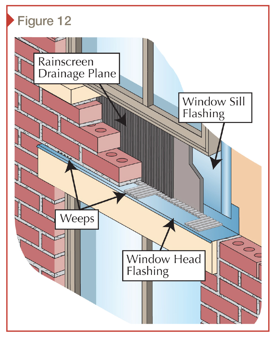
Zone 3 is the group of six windows on the second and first floors on the right and left sides of the exterior building envelope (Figure 12). In many cases windows or numbers of windows should be grouped into a single risk zone because their moisture management details are so interconnected and interdependent.
Louvers and windows
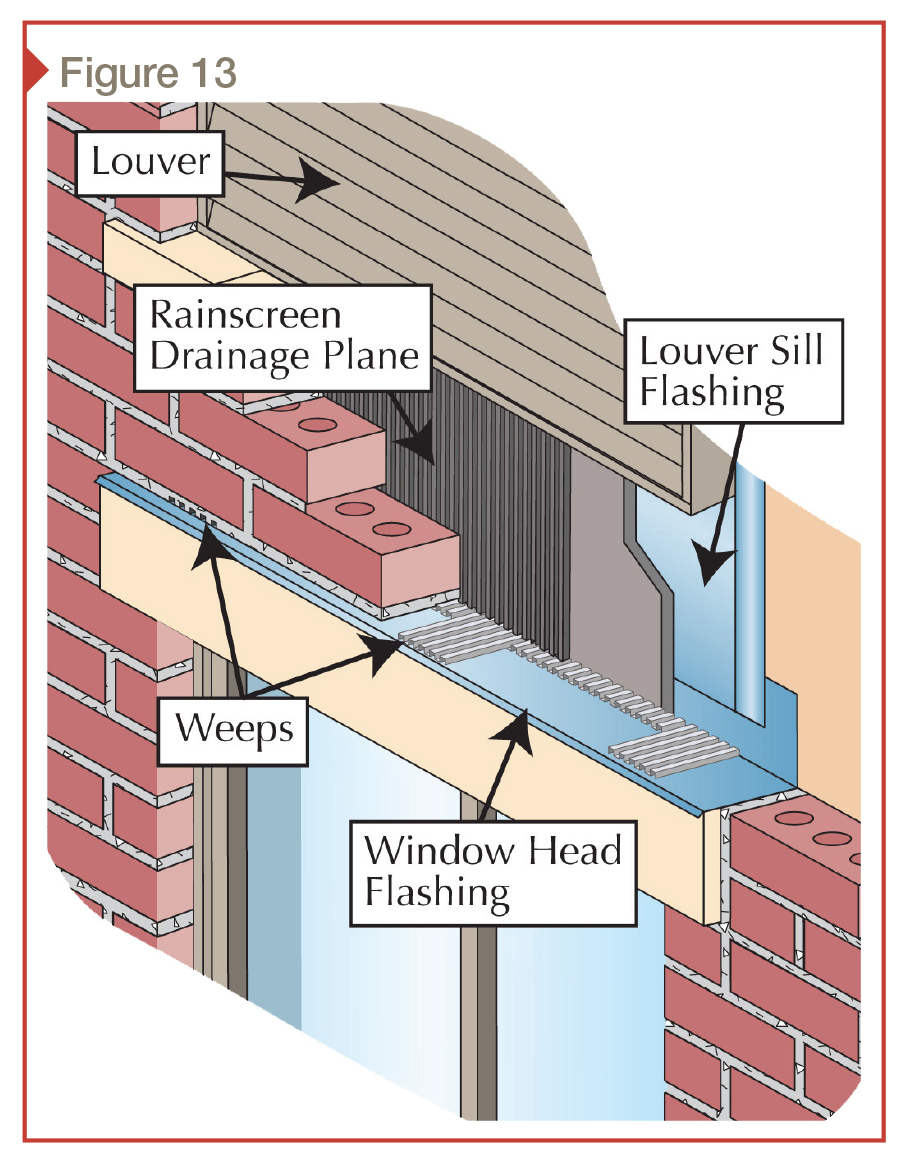
Zone 4 is the pair of louvers and windows on each side of the entryway (Figure 13). Obviously, the two types of openings are different, but the moisture management detail is virtually the same. Further, their proximity to one another joins them into one, unified moisture management risk zone.
In many circumstances, the wall opening directly above another opening will have an impact on the latter’s detail even though they may be of different types. The explanation is obvious: water runs downhill.
Arch above the door
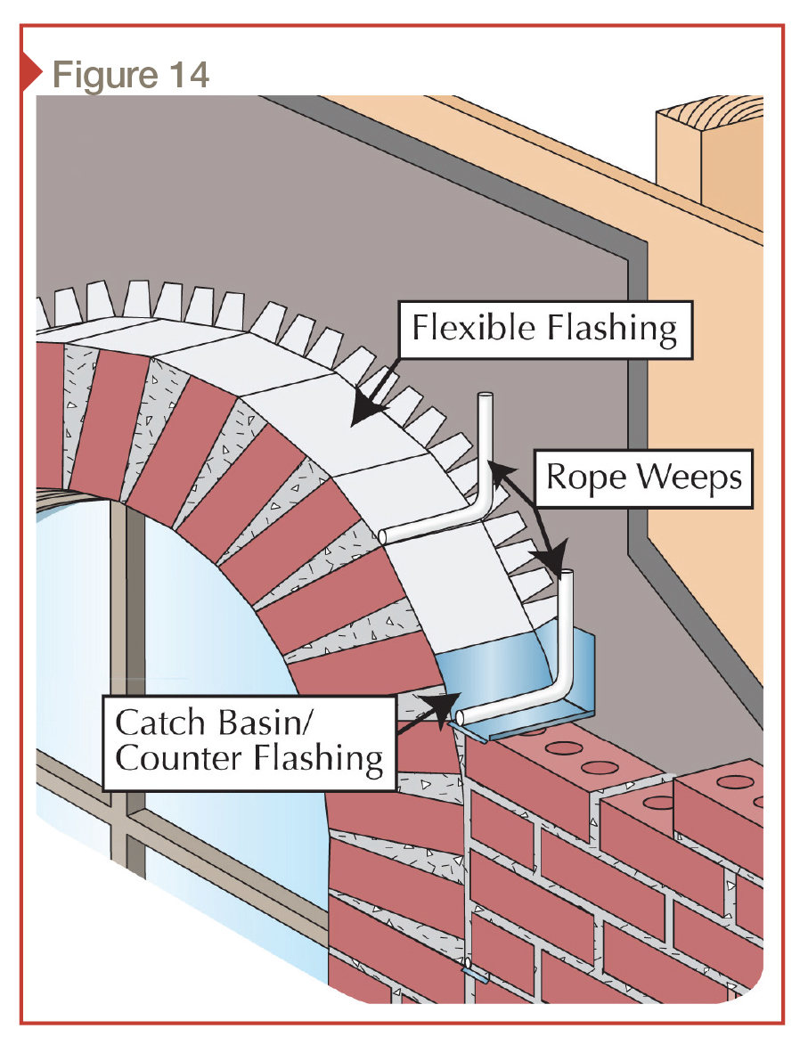
Zone 5 is the arch above the front entry (Figure 14). The arch is probably the most misunderstood moisture management detail of all the wall-opening details—for example, weeps protruding from the radius of an arch is not a good idea, but it still occurs.
If the weeps installed on the radius were to be functional at all, there would need to be an upturned stop flashing at that point of the arch flashing to stop moisture, and the weep would need to be installed at the bottom of the valley in the flashing. It would also have to have the same elevation in the masonry joint. The skill to execute this type of detail is difficult, if not virtually impossible, to find.
Like many good practices and details in the construction industry, the moisture management detailing for arches has been lost to history. Arches have been in common use since the time of the Romans, and so has the moisture management detailing required for their preservation. Nevertheless, most people today simply pass them off as decoration. The gaping mouths in the heads of animals and gargoyles that serve as column caps supporting arches on ancient and medieval structures are actually the weep exits (holes) for the arches’ moisture management system.
Decorative band stone
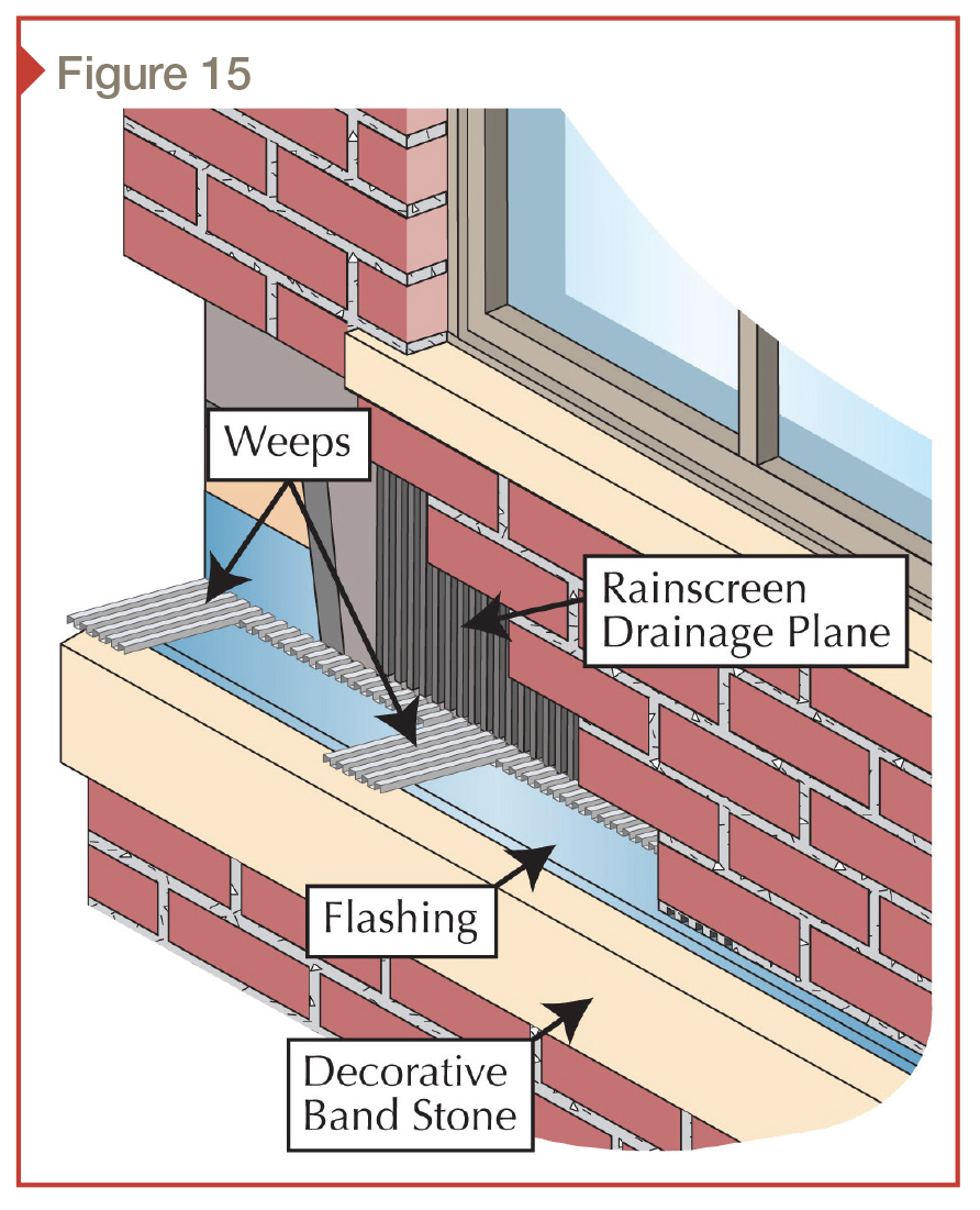
Zone 6 is the decorative band stone separating the bottom of the first floor exterior building envelope from the garden level exterior building envelope (Figure 15). This veneer detail has many responsibilities, including diverting moisture out, over, and away from the windows and wall below it. This decorative band stone also has an aesthetic appearance aspect.
Intersection of vertical wall and stoop
Zone 7 is the intersection of the vertical wall and the top surface of the non-frost affected stoop platform (Figure 16). This vertical wall veneer surface will be subjected to water splash back from the top surface of the platform of the stoop. Additionally, various types of ice control chemicals (e.g. salts and de-icers) may contaminate it, and snow removal tools (e.g. shovels and scrapers) may contract it. This wall detail needs to be durable, aesthetically pleasing, and backed by a waterproofing system because it is an exterior wall system with an interior living space behind it.
Front stoop steps and stoop platform
Zone 8 is the front stoop steps and platform. The seventh and eighth risk zones are the perfect example of the interdependence of moisture management systems. In the case of the stoop platform and steps, the slope-to-drain of the surfaces and their ability to resist moisture penetration is absolutely critical.

A detail that will allow for replacement of the stoop platform and steps without major impact on the veneer wall system is the appropriate design (Figure 16). This is an example of how a comprehensive understanding of moisture management risk zones influence the original building design and its detailing to allow for future maintenance, repair, and replacement of the exterior building envelope components with the least amount of interruption to adjoining details.
In this instance, the stoop platform is the construction detail that has the most exposure to moisture. In all likelihood, it will need to be repaired or replaced before the other adjoining details. The band of stone at the bottom of the vertical brick wall should be more durable than the brick. It separates the edges of the top surface of the stoop platform from the brick veneer and diverts water away from the intersection of this moisture sensitive detail.
Bottom of wall
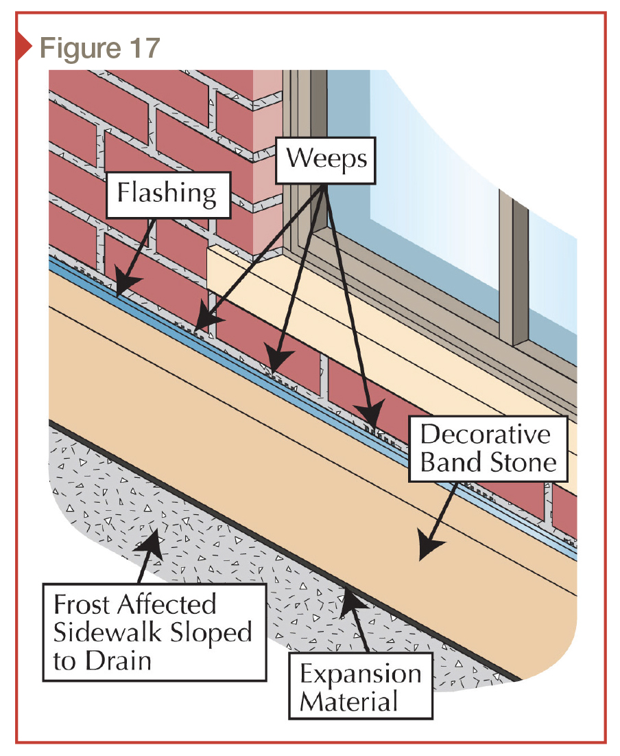
Zone 9 is the set of two garden level windows on each side of the front entryway stoop (Figure 17). Window openings at this elevation on an exterior building envelope have several unique moisture management concerns, including their proximity to grade level and accumulating moisture, along with the potential for splashes.

Designing/detailing the grade surface that adjoins these types of grade-level windows is an important factor that will play out in the daily maintenance and their long-term sustainability. The other obvious concern with windows in this location is security. A damaged window is also not waterproof.
On-grade
Zones 9 and 10 are the two on-grade details that contact the bottom perimeter of the building on each side of the front stoop (Figure 18). The grade surface in the first detail is a frost-affected sidewalk; the grade surface in the second is landscaping stone. These two very different ‘on-grade’ materials need to follow many of the same rules of good moisture management:
- They both need to maintain good slope-to-drain away from the structure they contact.
- Their top surface elevation must not interfere with the drainage weeps of other exterior building envelope components (these risk zones). Further, one must consider their movement up or down in elevation due to expansion or contraction of supporting soils due to the wetting, drying, or freeze-thaw of supporting fill material, or because of expansive soils.
- These details can never become attached to the structure they abut. The attachment and potential movement of these details will result in severe damage to the structure and the ‘at-grade’ details.
Conclusion
Understanding weeps and identifying unique moisture management risk zones on and in the exterior building envelope are critical for creating and maintaining a sustainable building. However, while these moisture management risk zones can be identified as separate and unique for the purpose of designing and detailing, they are not and cannot be disconnected from each other when it comes to moisture management.
From top to bottom and from bottom to top, they all interconnect and impact each other. No good wall system can survive a bad roof and no good roof can survive a bad wall system; they support and protect one another. This is what holistic and sustainable is all about—knowing that nothing is separate, all things are connected and nothing stands alone.
Notes
1 This reference comes from the 2006 edition—it is puzzling the reference to weeps was discontinued in the 2009 and 2012 versions of IBC given the importance of moisture management in the exterior building envelope. (back to top)
2 It should be emphasized, however, the ability of masonry cavity airflow to dry out or remove moisture is extremely limited. This airflow should not be expected to effectively remove or alleviate any type of ponding water condition—this should be the job of a well-designed weep system. (back to top)
3 Although this article concentrates on the wall portion of the exterior building envelope, it is important to remember many serious wall moisture management problems are actually caused by roof leaks, both low- and high-sloped. (back to top)
John Koester is the founder and CEO of Masonry Technology Inc. With construction experience dating back almost 40 years, he has been a card-carrying mason and cement-finisher, and for many years operated his own masonry construction business in the Minneapolis-St. Paul area. Koester has extensive background in waterproofing systems in the areas of forensics, design, and installation oversight—both in restoration and complete re-roofing projects. He can be contacted via e-mail at john@mtidry.com.
To read the sidebar, “Weep Now or Weep Later: Of Ropes and Tubes,” click here.


Hello Mr. Koester,
would the arch flashing and weep detail (figure 14) also work on a retrofit with a precast stone arch and brick veneer both on a masonry back-up? Could the brick veneer be removed from the spring line up, flashing and weeps installed and then brick re-installed?
Thank you in advance for your advice.
Andrew Feuer
Weep vents should be installed in the first course of masonry. Be careful with plastic corrugated weeps as showed in this article as they are prone to failure when installed on top of membrane flashing.
I have weep holes on each side of each brick on the outside of my house. Needless to say I have over 400+ weep holes on my one story 2400 square foot home. The diameter of the weep holes varies from 1 1/4″ to 3/8″ wide. Rodents are entering through the weep holes. I would like to fill in some of these weep holes every 2′ with mortar. On the remaining weep holes I will be placing weep hole covers. In your opinion is this feasible?
Thank you
James