Design without compromise: Balancing durable and energy-efficient buildings
Two critical aspects of sustainable construction are long-term durability and energy efficiency. The latter is a measure of whole building performance, which depends on the envelope as well as the building systems and occupant behavior. This article addresses the enclosure’s contribution to energy efficiency—namely its impact on heating and cooling loads and how to balance this with a need for durability.
Updated energy codes—such as American Society of Heating, Refrigerating, and Air-conditioning Engineers (ASHRAE) 90.1, Energy Standard for Buildings Except Low-rise Residential Buildings, and International Energy Conservation Code (IECC)—have heightened criteria for minimizing the enclosure’s thermal loads and reducing heat flow through the following mechanisms:
- conduction (through materials), which
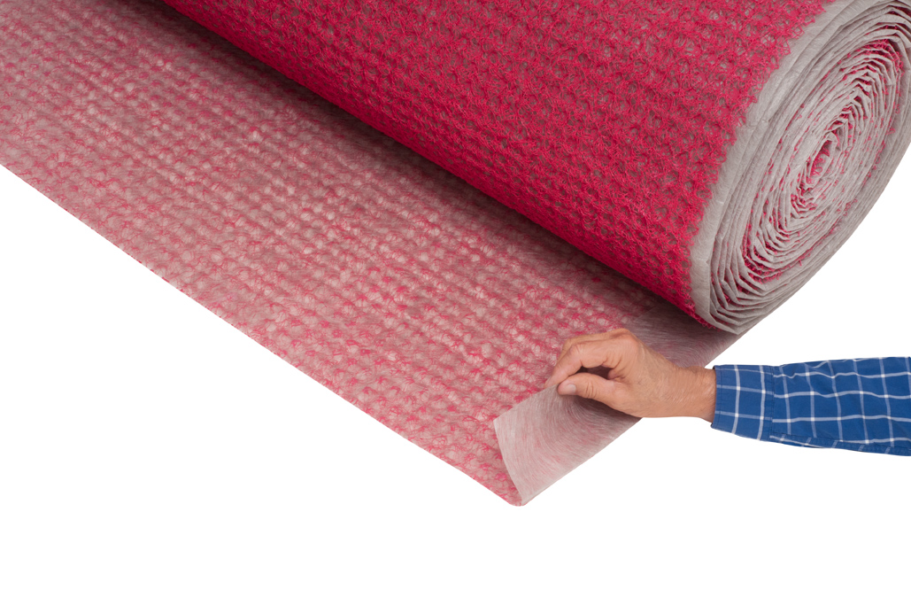
is controlled with thermal insulation (i.e. materials resistant to heat flow); - convection (through air currents), which is controlled with continuous air barriers (i.e. materials with high resistance to airflow); and
- radiation (through space), which is minimized with low-emissivity (low-e) surfaces (e.g. cool roofs or radiant barriers).
Durability of the building enclosure is especially critical because the expected service life is longer than mechanical, lighting, and water-heating systems. The major factors affecting the durability of multi-component building enclosure assemblies include heat, air, moisture transport, and material compatibility. The first two aspects are regulated through energy codes, but the potential impact and the unintended consequences of energy-efficient measures on moisture management are not well understood. A designer can significantly affect the service life of multi-component assemblies through selection of compatible materials, placement of materials within the building assembly, and design detailing.
This article examines recent energy code changes (excepting fenestration) for the opaque building enclosure, how these changes impact wall assembly design and long-term durability, and how moisture analysis tools can assist in selecting the optimum design option.
Trends in energy codes and wall assembly design
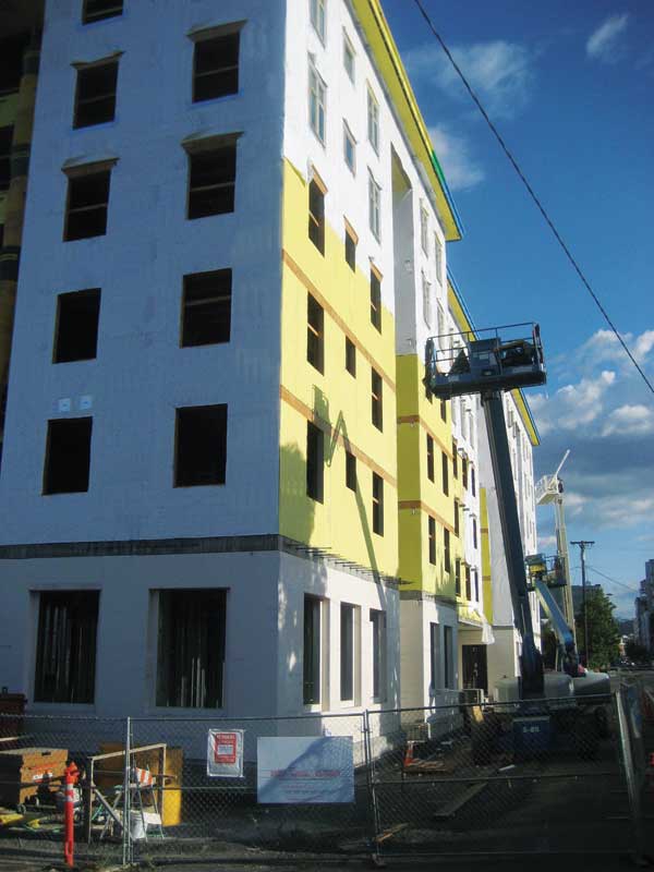
Building energy codes require increasing levels of thermal control for the building enclosure. Recent measures include increased insulation R-value, continuous insulation (ci), and continuous air barrier requirements. These measures reduce the envelope thermal loads and increase energy efficiency. However, the manner in which additional thermal insulation is added to framed wall assemblies is critical to their durability.
Prescriptive thermal insulation requirements for the last three versions of IECC and ASHRAE 90.1 are outlined in Figure 1 for non-residential steel-stud-framed wall construction. (Similar trends are common in residential occupancies, but the requirements are slightly more stringent.)
The main trends include increased overall R-value for thermal insulation as well as the expanding of ci requirements to more climate zones. The green-shaded cells in Figure 1 highlight the zone in which continuous insulation becomes mandatory for each code version. For example, the ci requirement begins in Climate Zone 5 for 2006 IECC, Zone 3 for 2009 IECC, and in all zones for 2012 IECC. ASHRAE 90.1 shows similar trends in ci requirements. In wood-stud construction, continuous insulation for the prescriptive compliance option is required in fewer climate zones.
In addition to increasing the R-value for the walls, ci is very important for reducing the thermal bridging that can significantly decrease the cavity insulations effective R-value. Thermal bridges are regions with high thermal conductance that bypass thermal insulation leading to large thermal losses, and are very significant for steel-stud construction.
Figure 2 shows a few examples of the impact of thermal bridging and the framing factor on the effective R-value of cavity insulation in steel-framed walls. As a result of these losses, ci is often required for prescriptive compliance options. The new requirements led to changes in wall assembly design for framed construction. The basic types of framed wall construction are shown schematically in Figure 3, but other combinations are also often used.
Various moisture analysis tools for durability assessment
Energy code criteria for reduced heat flow across the building enclosure contributes to increased building envelope efficiency. However, reduced heat flow also slows down the wall’s ability to dry, which may increase the risk of moisture-related issues under certain conditions. Building assemblies may start out, or periodically become, wet, but can have an acceptable performance and provide a long, useful service life when allowed to dry. Problems occur when buildings stay wet long enough under adverse conditions for materials to deteriorate.
Moisture analysis is often required to estimate potential durability risks due to changes in wall assembly design, construction practices, and new materials. The tools commonly used for moisture analysis include dewpoint calculation and Wärme und Feuchte Instationär (WUFI) analysis, which is German for ‘heat and moisture thermodynamics’. (WUFI was developed in Germany by Fraunhofer Institute for Building Physics [IBP], in collaboration with Tennessee’s Oakridge National Laboratory [ORNL]. )
While determining dewpoint temperature and location within the building enclosure can provide useful design guidelines, relying solely on this calculation has significant limitations as it is based exclusively on vapor diffusion equations and cannot simulate other, more important moisture sources (e.g. air-transported moisture, incidental rainwater intrusion, and wet construction materials. The analysis also assumes steady-state, equilibrium conditions.
Dewpoint calculation is performed for the coldest temperature of the year while assuming interior and exterior conditions are fixed and associated with that particular point in time. These assumptions have serious limitations since equilibrium conditions are never reached in an open system (i.e. since the building assembly is not in a controlled environment, it is ‘open’ to continuously changing exterior climate parameters).
Unlike the dewpoint analysis that assumes steady-state conditions, WUFI is a dynamic simulation for coupled heat and moisture transport, using hourly climate data and transient parameters. Even though the WUFI model is based on vapor diffusion equations, it can simulate the impact of other moisture sources and design conditions such as ventilated cladding.


Sign up for our weekly newsletter
Architectural materials and methods delivered right to your inbox
- CSI News and Notes: CSI Foundation’s construction camp; CSI spring exam; and more
- CSI News and Notes: CSI’s credentials; CSI conference theme; and more
- To be specific – CSI supports young AECO professionals
- CSI News and Notes: CSI’s foundation scholarships, national conference, and Crosswalk
- CSI News and Notes: AI’s impact; CSI 2024 conference, and more
Related Products
Read the Latest Issue