Failures: Persistent water leakage above ribbon windows
In contemporary brick cavity wall construction, the performance of the wall assembly is dependent on the proper design and construction of a dedicated drainage cavity to properly manage bulk water that penetrates the brick cladding.
A critical component of the drainage cavity is the water-resistive barrier (WRB) that is located at the innermost plane of the cavity (or wet zone) of the wall assembly. However, to effectively manage water within the cavity, the WRB must be integrated with a through-wall flashing (TWF) at horizontal interruptions in the cavity (e.g. wall bases, heads
of openings, shelf angles, etc.) to effectively redirect water within the cavity to the exterior.
The Brick Industry Association (BIA) provides recommendations to maximize water penetration resistance of cavity wall construction in its Technical Notes on Brick Construction Series—Technical Note 7, including:
- Provide an unobstructed air space clear of mortar that maintains a minimum clear cavity of 25.4 mm (1 in.) inboard of the brick.
- Flashings can consist of sheet metal pans or a combination of flexible membranes and metal drips. Flashings should extend vertically a minimum of 203 mm (8 in.) onto the backup wall and terminate either flush with (or preferably beyond) the exterior face of the brick and be formed with a drip to direct water away from the wall.
- Integrate the WRB with the TWF in a shingled fashion.
- Support flexible flashing materials across gaps and openings. Flashing should be fully adhered to the substrate to prevent lateral migration of water should a breach occur.
- Lap plain flexible flashing components a minimum of 152 mm (6 in.), and self-adhering membrane flashing in accordance with manufacturer installation guidelines. Seal overlapping components and exposed edges with continuous lines of a compatible sealant, adhesive, or liquid membrane. Splices in metal flashings/drip edges can consist of simple lap splices or cover plates. Maintain continuity of flashings at planar transitions (corners, projections, etc.).
- Terminate ultraviolet (UV)-sensitive flashing material inboard of the exterior wall face and integrate it with the underlying sheet metal flashing or drip.
- Install weeps directly above the through-wall flashing to promote unrestricted drainage.
- Where flashing is not continuous, provide end dams to mitigate the lateral migration of water.
When through-wall flashing is not properly detailed or installed in cavity wall construction, the water penetration resistance of the enclosure can be compromised. This was recently observed at a multi-story office building in the southeastern U.S., that regularly experienced water leakage during prolonged rain events above ribbon window assemblies.
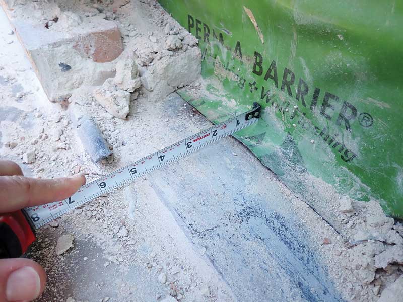
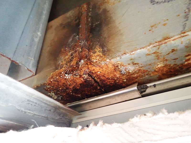
Review of the as-built construction revealed a through-wall flashing that did not adequately protect the continuous relieving angle above the window or manage water within the wall cavity. As installed, the flashing consisted of a flexible membrane that extended from the exterior sheathing to approximately 25.4 mm (1 in.) onto the horizontal leg of the angle—water collected on the angle at the base of the cavity and entered the building through gaps in splice joints between angle sections.
 Jeffrey Sutterlin, PE, is an architectural engineer and associate principal with Wiss, Janney, Elstner Associates’ (WJE’s) office in Princeton, New Jersey. He specializes in investigation and repair of the building envelope. He can be reached at jsutterlin@wje.com.
 David S. Patterson, AIA, is an architect and senior principal with Wiss, Janney, Elstner Associates’ (WJE’s) office in Princeton, New Jersey. He specializes in investigation and repair of the building envelope. He can be reached at dpatterson@wje.com.
The opinions expressed in Failures are based on the authors’ experiences and do not necessarily reflect that of The Construction Specifier or CSI.
Sign up for our weekly newsletter
Architectural materials and methods delivered right to your inbox
- CSI News and Notes: CSI Foundation’s construction camp; CSI spring exam; and more
- CSI News and Notes: CSI’s credentials; CSI conference theme; and more
- To be specific – CSI supports young AECO professionals
- CSI News and Notes: CSI’s foundation scholarships, national conference, and Crosswalk
- CSI News and Notes: AI’s impact; CSI 2024 conference, and more
Read the Latest Issue