Durability of Brick Veneer: A deeper look at masonry anchors
by Brett T. Fagan, PE, Nickie M. Ramm, PE, and Beth Anne Feero, EIT
Masonry veneer failures where the brick falls away from the wall can be traced to fastener pull-out, improper embedment of the tie into the mortar, poor bond between the tie and mortar, poor mortar quality, and tie corrosion. The question is, how can this be prevented?
Ideally, the designer of record for brick masonry veneer anchors (commonly known as brick ties) would be clearly defined in the contract documents, but several parties are usually involved. The architect often includes a specification and the structural engineer will provide a lintel angle design, but there are other details, unique to each building, that require specific solutions for the anchor type, spacing, and layout. The spacing and layout appear to be determined by the mason or laborers during installation, which relies on their training, experience, and understanding of the code requirements.
On a recent multi-family residential project, a worst-case example of the minimal direction provided for masonry anchor installation was observed. The anchors were apparently installed as the brick was laid; the spacing was dependent on the installer. A review of the design documents showed there was no direction to address installation challenges, such as changes in the framing spacing and in the brick profile. Installation errors and omission of anchors at these locations are a safety issue for pedestrians and building tenants. While the building code and industry standards provide general requirements with seemingly simple application during construction; dealing with the architect’s aesthetic desires may demand a variety of anchor installation solutions on a single project.1

Codes and specifications
Requirements for brick tie installation are governed by Chapter 6 of American Concrete Institute/American Society of Civil Engineers/The Masonry Society (ACI 530-05/ASCE 5-05/TMS 402-05), Building Code Requirements and Specification for Masonry Structures and Related Commentaries, also known as the Masonry Standards Joint Committee Code (MSJC). It provides the installer with prescriptive design requirements for common veneer construction conditions, such as regularly spaced openings within a flat masonry wall.
The discussion in this article is applicable to unit masonry, defined by the ability to place the masonry with one hand. Masonry that is too large to set with one hand requires an engineered solution, such as kerf anchors. Alternative design methods, as described in MSJC 6.2.1, can also be used in lieu of the prescriptive methods discussed for unit masonry. Alternate designs require an engineering analysis by the designer of record considering support, deflection, stiffness, strength, corrosion, and weatherproofing of the assembly.
According to 2011 MSJC provisions, two-piece adjustable anchors, nine-gage wire ties, and corrugated steel ties are to be installed with a maximum area per anchor of 0.25 m2 (2.67 sf). For multi-family wood-frame construction with studs at 305 mm (12 in.) on center (oc), the anchors require horizontal spacing of 610 mm (24 in.) to hit the studs, and thus the maximum vertical spacing would be 406 mm (16 in.). The horizontal and vertical spacing is reversed when the studs are at 406 mm.
On projects with changes in framing, wood trusses at floor lines, or expansion joints that fall on a stud line, the spacing of anchors would have to be modified to maintain the maximum tributary area. The maximum horizontal spacing is limited to 812 mm (32 in.), which would be two stud spacings on a wall with studs at 406 mm oc. The maximum vertical spacing is 635 mm (25 in.). These maximum spacings cannot exist at the same time since the area would cover 0.4 m2 (4 sf), exceeding the 0.25-m2 (2.67-sf) limit.
Code provisions do not permit use of corrugated or nine-gage wire ties in steel-stud construction; adjustable anchors are required for steel backing.2 For anchors other than those described above, the maximum area per anchor is permitted to be 0.3 m2 (3.5 sf)—this includes anchors such as dovetail and two-seal screw ties.3
Design challenges
Specifying only the maximum spacing limits and tributary area for each anchor leaves the actual spacing up to the installer. If the installer decides to always increase the anchor spacing or leave out anchors when the spacing geometry is interrupted, the consequence may be an inadequate number of veneer anchors. The designer can reduce interpretation in the field by limiting anchor spacing by the number of brick courses vertically or head joints horizontally.
Framing spacing
Traditional wood frame structures maintain equal spacing between studs at all levels. Framing installation where the stud spacing is adjusted at each level to accommodate decreased loading and wood shrinkage factors is common in modern design practice. One example would be 305-mm (12-in.) stud spacing at the lower two levels, increasing up to 406 mm (16 in.) at the third and fourth levels. The mason must accommodate this adjustment by installing the anchors at 610 mm (24 in.) horizontally and 406 mm vertically at the lower levels, to installing at 406 mm horizontally and 610 mm vertically at the upper levels.
Additional anchors
Additional anchors are required by MSJC for openings larger than 406 mm. Openings would be defined as fenestrations in the masonry veneer, including features such as windows, doors, and balconies. Additional anchors are to be provided around the perimeter of the opening at 1 m (3 ft) oc or less, and they should be placed within 305 mm of this opening.
A 1.5 x 1-m (5 x 3-ft) window would require two additional anchors along the jambs, and one additional anchor at the window head and sill. The anchors at the openings are required in addition to the standard pattern of anchors in the field of the wall. Care must be taken by the installer to avoid penetrating the lintel angles or through-wall flashing at window heads.
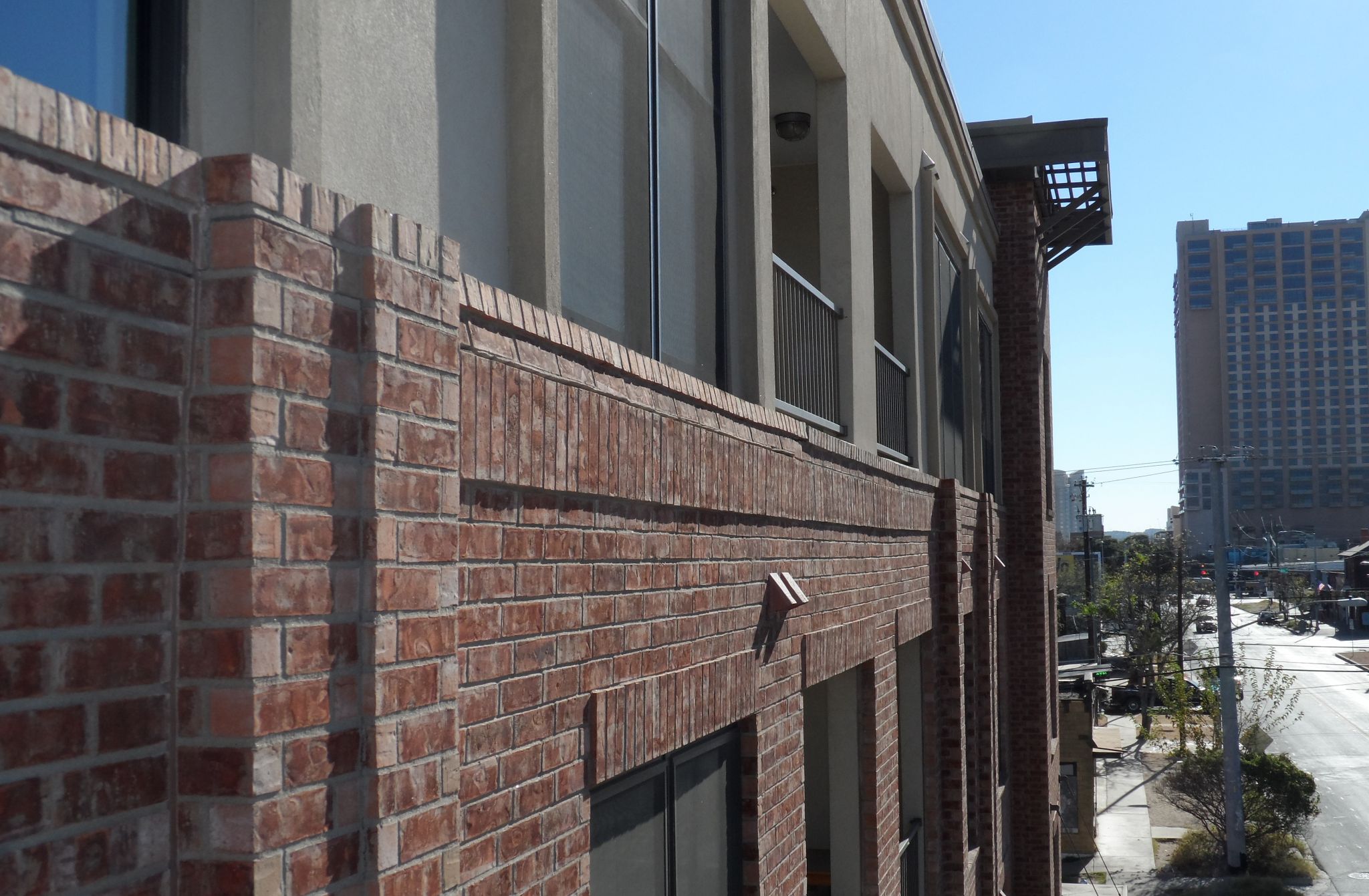
Expansion joints are not classified as an ‘opening,’ and therefore do not require additional anchors; however, the anchor spacing should be adjusted at each side of an expansion joint (Figure 1) to accommodate the wider horizontal spacing, specifically in wood-framed construction with studs spaced 406 mm oc. This is illustrated in Figure 2 where the horizontal spacing is increased to 812 mm (32 in.) oc as a result of the expansion joint at the window jamb, requiring the vertical spacing to be reduced to 305 mm oc.
Fasteners
Another challenge rarely addressed in design documents or building codes is the type of anchor and fastener; both depend on the substrate to which the brick anchors. According to the MSJC, anchors attached to wood studs are to be fastened using a corrosion-resistant 8d common nail (64 mm [2.5 in.] long) or a fastener with equivalent pullout strength. (The approximate pullout design value is 534 N [120 lb] for an 8d common nail with 16-mm [5/8-in.] sheathing over wood stud framing.4) In steel stud construction, anchors are to be fastened using a No. 10 corrosion-resistant screw or better.
The MSJC only describes a single fastener in each anchor for wood framing. This does not mean an adjustable back plate can use two nails smaller than 8d to equal one 8d nail, due to the pullout behavior when loaded in tension. While the nails would share the load under tension, the anchor attachment fails when the first fastener fails (Figure 3). To meet the code required capacity, each fastener installed should have a capacity at least equal to an 8d common nail.
Fastener size is also important in regard to varying sheathing thickness or substituting anchors. The MSJC states to use an 8d nail or equivalent, but there is no specific sheathing reference to assist with interpreting the strength basis of the code requirement. One interpretation is it refers to a single layer of 13-mm (1/2-in.) sheathing. In certain conditions where the walls use double sheathing, an increased fastener size would be required to provide equivalent pullout strength. For wood studs, this would change the fastener type to a 10d common nail as a replacement for the 8d common nail used in single sheathing applications.
As an alternate, the Federal Emergency Management Agency (FEMA) recommends specifying a 51-mm (2-in.) minimum nail embedment.5 The pullout strength can also be improved by using ring-shank nails.
![Anchors failed, resulting in 76-mm (3-in.) sagging of veneer. When the first fastener fails at the bottom of the anchor, the anchor loses all capacity. The result is large movement of the brick masonry. At [right/below], the top fastener failed, leading to anchor capacity loss. The fastener shown is neither the right size nor type for masonry anchor use.](http://www.constructionspecifier.com/wp-content/uploads/2014/04/CS_January_2014_HR-56.jpg)
The substrate may change multiple times within the same exterior elevation. A typical elevation in multi-family wood-frame construction could include wood studs, a concrete masonry infill wall at locations such as elevator cores, light-gage steel framing at a retail storefront, and a concrete perimeter beam at the podium slab. In each of these conditions, the anchors, fastener type, spacing pattern, and cavity width may change.
Written instruction should be included to direct the installer regarding changes in anchor type and spacing. It is equally important the design professional remain involved during construction, periodically observing the as-built construction and offering guidance for conditions as they are encountered.
During an interview, a local masonry contractor reported that without specific instructions, the installers would usually be equipped to install only one type of anchor. When a different substrate is encountered, the region is skipped, with the intention of returning to install different anchors. Forensic investigations that have questionable masonry indicate this second pass may be completed with the anchors on hand or skipped again, resulting in inadequate masonry anchorage.
Changes in substrate or variation in the plane of the wall also leads to cavity width variation requiring a different type and wire size (for two-piece anchors). In many observed cases, brick anchors are omitted or incorrectly installed in these locations due to a lack of design, as well as installers using the materials on hand to cope with the changes in conditions.
Layout adjustments at floor lines
Wood trusses used in multi-family construction interrupt the studs at floor lines. The spacing of the web of the truss can vary from the stud spacing, forcing a change in the fastener layout. MSJC does not differentiate between the wall studs and the web of wood trusses for the attachment of masonry anchors—for installation purposes, however, the anchors should not be placed in the web unless there are no other options. By skipping the joist web, the designers can maintain the anchors’ vertical alignment. This eliminates anchors placed off the vertical line of anchors attached to the wall studs. It also stops the installers from puncturing the sheathing when looking for the joist web members.
Architectural details
Aesthetic design choices also affect the anchor spacing, resulting in a change in spacing and type. Stack-bonded masonry is often added at perimeters of opening or at accent panels; the change in bonding pattern requires the addition of horizontal joint reinforcement. MSJC requires W1.7 (9 gage) wire horizontal reinforcement at 457 mm (18 in.) oc vertically for masonry installed in bonding patterns other than running bond. This provision also includes the joints above or below rowlock courses often used at window sills and soldier courses used at floor lines and window heads.
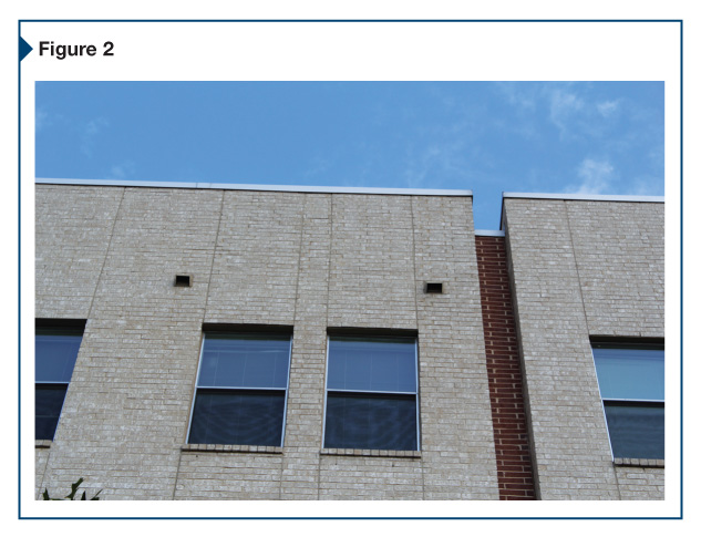
Architectural reveals in the form of bump-outs and recesses (Figure 4) within the plane of the wall present a challenge in maintaining proper embedment of the wire tie. Column elements with excessive cavity widths (generally larger than 76 mm [3 in.] from the inside face of the veneer to the outside face of the structure) require specialty, high-strength anchors designed to span larger cavities and maintain the required 38-mm (1.5-in.) embedment in the mortar joint. The designer of record should provide written guidance and perform observations of the as-built conditions to ensure proper anchorage is provided for the design challenges presented, as well as for additional locations that have not been discussed.
Recommendations
Designers can avoid many challenges and installation miscues if they provide a written specification for the masonry anchors responsive to the details in the drawings. It is recommended to include the following requirements for proper anchor selection and installation:
- Provide specific anchor and fastener for each type of structural framing support with masonry cladding.
- Specify anchor spacing based on the maximum brick courses between anchors. For example, a spacing of 610 mm (24 in.) oc horizontally and 406 mm (16 in.) oc vertically is equivalent to one anchor every three head joints horizontally and four courses vertically for common modular brick sizes.
- Cavity width changes should be accommodated by different sized wire ties; wire ties should not be bent or deformed to span the cavity space.
- Install additional anchors placed within 305 mm (12 in.) of an opening, spaced at 1 m (3 ft) oc around the perimeter of the opening.
- Notify designer if unforeseen conditions are encountered during anchor installation.
This article considers masonry veneer anchors and their use in common conditions; additional anchor capacity would be needed for seismic or high-wind applications. Further, the impacts of masonry anchors on the waterproofing of the exterior building were not discussed; waterproofing of the cavity wall is essential to the structure’s durability, and must not be overlooked. Architects, engineers, and masons should collaborate to determine rational, feasible, and code-compliant solutions for anchoring masonry veneer to provide a secure, durable cladding.
Notes
1 The authors gratefully acknowledge the continuing support and leadership of David W. Fowler, PhD, PE—the faculty advisor for the research being performed at the Durability Lab, a testing center at The University of Texas at Austin. (back to top)
2 See the Masonry Construction item, “Avoid Corrugated Ties with Steel Studs,” in the June 1995 issue. Visit www.masonryconstruction.com/metal/avoid-corrugated-ties-with-steel-studs.aspx. (back to top)
3 For more, see Paul Curtis’ article, “Masonry Anchors and Ties by the Code: Anchors, Connectors, and Fasteners,” in the September 2012 issue of Masonry Magazine. Visit www.masonrymagazine.com/features/1408-masonry-anchors-and-ties-by-the-code.html. (back to top)
4 For more information, see “Commentary Part XII: Nails and Spikes” in the 2004 National Design Specification for Wood Construction, published by the American Forest & Paper Association (AF&PA). (back to top)
5 See FEMA’s 2005 “Attachment of Brick Veneer in High-wind Regions” on www.fema.gov/pdf/rebuild/mat/brick_veneer.pdf. (back to top)
Brett T. Fagan, PE, is a principal of Building Diagnostics Inc., specializing in the investigation of problems with existing buildings, designing remedies for those problems, and resolving disputes which arise from them. He is a licensed professional engineer, and participates in the research being performed at The Durability Lab—a testing center established by Building Diagnostics at The University of Texas at Austin. He can be reached by e-mail at bfagan@buildingdx.com.
Nickie M. Ramm, PE, is a senior engineer at Building Diagnostics, where she specializes in failure investigation, remedial design, architectural peer review, new construction monitoring, and diagnostic testing for building envelope systems. Ramm also participates in the company’s research group, The Durability Lab, which researches and tests the durability of building components, identifying factors causing premature failure. She can be reached via e-mail at nramm@buildingdx.com.
Beth Ann Feero, EIT, is completing her master’s degree in architectural engineering at the University of Texas at Austin. She is a graduate research assistant in The Durability Lab. She can be reached via e-mail at bfeero@buildingdx.com.
To read the sidebar, click here.
Sign up for our weekly newsletter
Architectural materials and methods delivered right to your inbox
- CSI News & Notes: CSI’s impact earns official recognition; celebrate leaders, mentors, and innovators; and more
- CSI News and Notes: CSI spring certification exams open; scholarships available; and more
- CSI News & Notes: CSI MSR heading to San Diego; spring certification exams open; and more
- To Be Specific: Why CDT Should Be Your First Move
- CSI News & Notes: CSI Fellows share member benefits; and a New Year’s Resolution to keep
Products


Read the Latest Issue