


by Pamela Androff, EIT, LEED AP
Variable refrigerant flow (VRF) zoning is poised for dramatic growth, not only because of its energy-saving benefits and precise zone control, but also due to expanding government mandates and its ability to contribute to Leadership in Energy and Environmental Design (LEED) certification.
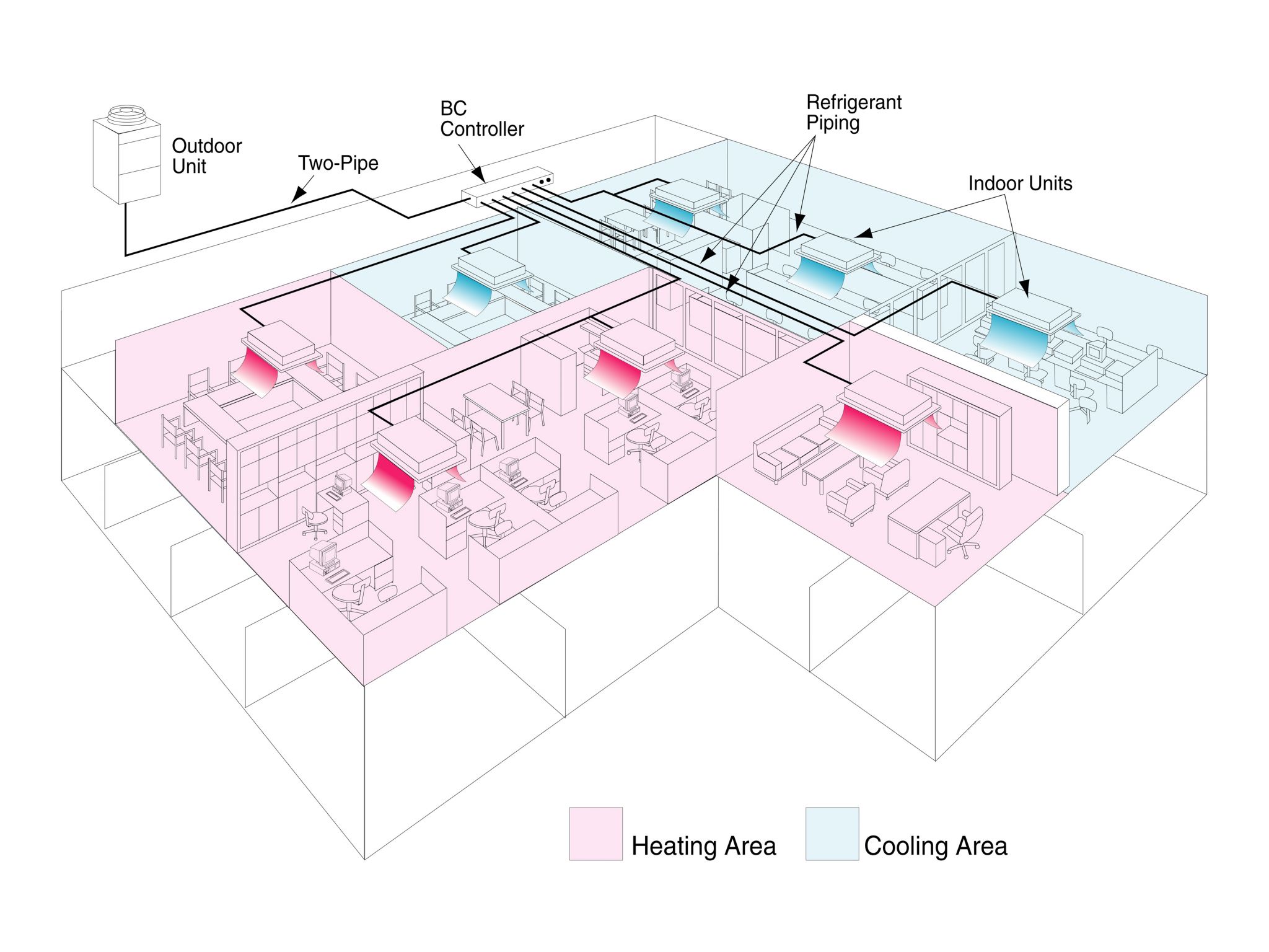
HVAC technologies play a vital role in meeting sustainability and energy efficiency construction specifications. VRF zoning involves a flexible, split-type system using an air-source outdoor unit or water-source unit, and indoor air-handling units (AHUs) individually placed within a building’s zones. The system provides precise comfort control by moving refrigerant through piping from the outdoor unit to the zones to be cooled or heated. The outdoor units are compact, with various styles of interior AHUs offering a range of design capabilities.
As the technologies are so different, it can be challenging to compare the energy-efficiency data of traditional commercial HVAC systems with VRF zoning systems. This article answers five questions specifiers should ask about energy-efficiency data for VRF zoning and other HVAC systems. An overview of major commercial HVAC systems, description of VRF zoning technology, and details about VRF zoning’s features and benefits is also discussed.
HVAC systems overview
The four main HVAC systems architects and engineers specify for new construction and retrofits are:
- packaged systems;
- variable air volume (VAV) systems;
- geothermal systems; and
- VRF zoning systems.
A traditional packaged system is usually contained in one unit and often includes traditional boilers, chillers, packaged terminal air conditioners (PTACs), water-source heat pumps, and multi-zone rooftop units—essentially any system based on water or direct expansion (DX). Typically, conditioned air moves from the system’s central blower to the indoor space through a series of long duct runs.
A VAV system consists of an AHU or packaged HVAC unit providing air supply at a constant temperature of approximately 12.8 C (55 F). A VAV terminal unit, or box, controls the temperature at each zone. If a zone requires cooling, the damper in the VAV box modulates to allow the appropriate amount of air into the space. Heating occurs at the zone level and requires a local heat source, which is generally an electric resistance heater or hydronic heating coil mounted in the VAV box.
A geothermal system features a loop, or ground heat exchanger, that extracts heat from the earth using an underground piping system. The piping typically consists of a specified size and number of high-density polyethylene (HDPE) coils filled with an antifreeze-water solution that is circulated between the exchanger and the heat pump.
VRF zoning difference
The key difference between VRF zoning and other systems is the method of delivering conditioned air. The former measures temperature in each zone, and reacts to changes in cooling and heating requirements by varying refrigerant flow between indoor and outdoor units. Conventional systems, on the other hand, react to temperature change by activating a central system and moving chilled or heated air through long runs of ductwork. Since VRF zoning systems do not require long duct runs, the building avoids the potential energy loss of at least 30 percent, that is associated with central forced-air systems.
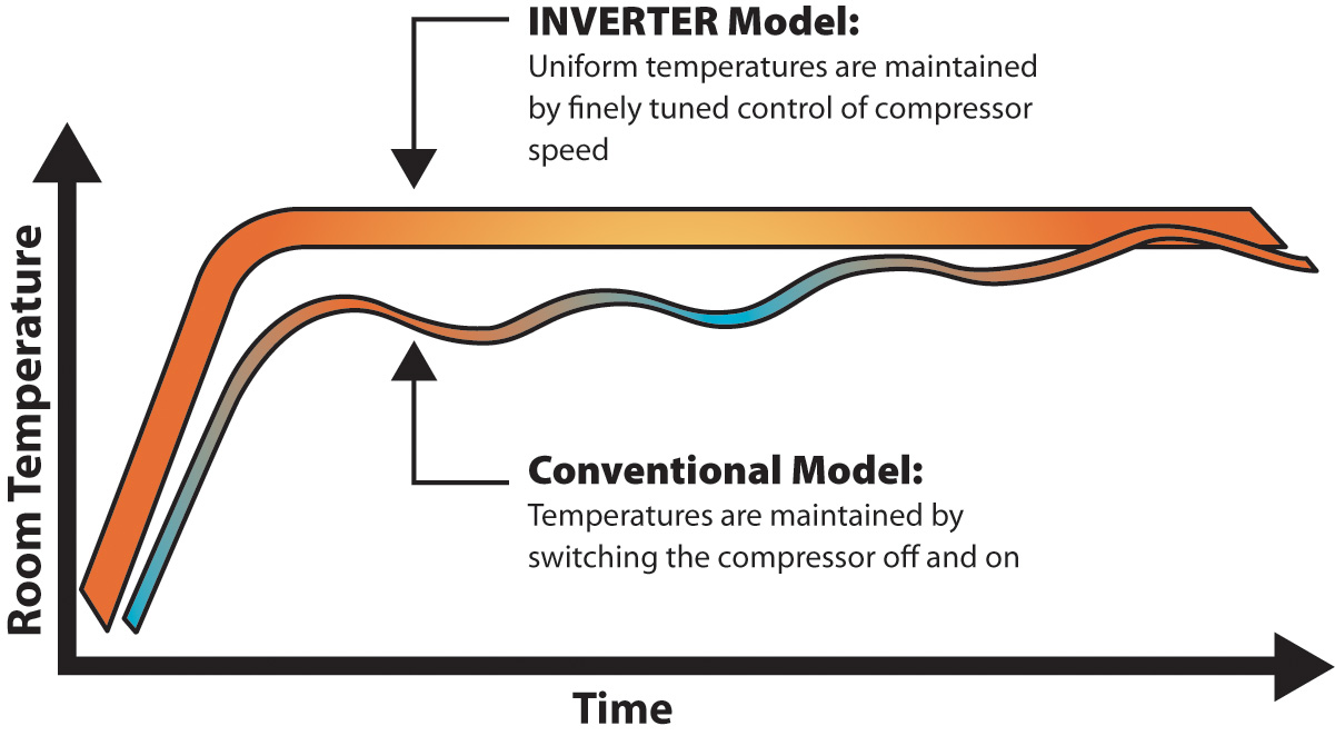
One of the major functional benefits of VRF zoning systems is increased energy efficiency. The system’s inverter-driven compressor motor ramps up its rotation frequency rate until a set temperature is met, and then varies its speed to maintain the desired comfort level. Typically, a compressor runs at partial speed to maintain the desired capacity. The inverter-driven compressor avoids the abrupt, energy-consuming start-and-stop of traditional HVAC systems, saving energy while preventing power surges to the building’s electrical system. A longer lifespan is also achieved with this smoother operation characteristic.
Intelligent VRF zoning technology also provides constant communication throughout the system, and performance data is saved for verifying and measuring energy efficiency over time.
Besides being highly energy efficient, VRF zoning systems allow for design and installation flexibility. The compact air-source outdoor units, water-source units, indoor units, and other components can be installed in tighter outdoor and indoor spaces because they require less piping and duct space. Generally, units include two refrigerant pipes with non-polar, two-wire control connections equating to faster installations. Additionally, specific trades such as chilled water and boiler technicians, control contractors, or well-drillers are not required—this reduces the installation cost.
In many buildings, the mechanical equipment dictates plenum space requirements. Running smaller VRF zoning refrigerant piping results in more usable space. If enough space is saved throughout the building, an extra floor can be added without increasing the structure’s overall height.
VRF zoning systems can be up to 30 percent lighter than chilled-water systems, resulting in easier handling, less transportation cost, and reduced structural support. For example, the smaller footprint of a VRF zoning 6-ton outdoor unit, 920 x 740 mm (36.2 x 29.1 in.), allows the equipment to be transported to the top of a building via the service elevator, saving the cost of a crane. When larger system capacities are required, multiple outdoor units are employed. This allows the load to be distributed across the existing structure or avoided by mounting on the ground.
For the interior, various indoor unit styles include wall-mounted, floor-standing (concealed and exposed), and vertical-concealed. Ceiling options include suspended, recessed, and concealed ducted. The net benefit of these options is a customizable building comfort solution offering greater design flexibility. Each indoor unit style offers its application advantages. Ductless options tend to be well-suited for renovation projects where moving walls or ceiling structure is not recommended. New construction projects tend to favor the ducted options where indoor units can be designed discreetly within the building’s framework.
Finally, the total installed cost of a VRF zoning system is less than or equal to the total installed cost of most conventional systems. Maintenance is greatly reduced and requires no special trades to perform the simple functions of changing/cleaning filters and cleaning outdoor condensing units. Software tools also assist in easier trouble-shooting and maintenance.
![Due to the steep roof and thick roof walls, VRF zoning systems were the only heating and cooling option for this adaptive reuse project. [CREDIT] Photo © Alan Gilbert Photography](http://www.constructionspecifier.com/wp-content/uploads/2014/05/Union-Mill.jpg)
![The Mercy Corps world headquarters (Portland, Oregon) used VRF zoning systems to help achieve Leadership in Energy and Environmental Design (LEED) Platinum certification. [CREDIT] Photo © Jeff Amram. Photo courtesy Mercy Corps](http://www.constructionspecifier.com/wp-content/uploads/2014/05/Mercy-Corps.jpg)
When specifying a VRF system the following questions should be considered.
What do the efficiency terms EER, IEER, COP, and SCHE mean?
Energy efficiency ratio (EER) is a measurement of the cooling capacity for a unit (in Btu/hour) divided by the electrical energy it uses (in watts) at a specific outdoor temperature typically provided at 35 C (95 F). This metric is typically used to measure the full load efficiency of a system. Based on the weightings used in the integrated energy efficiency ratio (IEER) metric, this operation occurs only about two percent of the year and never in climate zones not reaching 35 C (95 F) outdoor temperature.
IEER is an expression of the system’s cooling part-load efficiency based on a weighted average combination of the system’s EER at four points defined by the load percentage. The system is measured at 100, 75, 50, and 25 percent capacity, with the highest weighting given to the 75 and 50 percent capacity operation, making IEER a good cooling season efficiency indicator.
Coefficient of performance (COP) is the ratio of output energy divided by the input energy. It is normally used to measure efficiency in the heating mode for heat pumps. COP ratings are typically displayed at 8.3 C (47 F) and –8.3 C (17 F). VRF zoning systems can typically achieve COP ratings of 3.5, and above at 8.3 C and because of the capabilities of the inverter-driven compressor to maintain capacity at lower temperatures, VRF zoning systems can achieve COPs well above 2 at –8.3 C.
![Taking advantage of an existing geothermal well field, the historic Muscatine County Courthouse (Muscatine, Iowa) used water-source VRF zoning systems. [CREDIT] Photo © OnSite Photography](http://www.constructionspecifier.com/wp-content/uploads/2014/05/Muscatine-County-2.jpg)
How can specifiers compare the efficiency data for traditional HVAC systems and VRF zoning systems?
Traditional unitary systems and VRF zoning systems share some of the same COP, IEER, and EER metrics. The EER values and COP values at 8.3 C (47 F) of unitary products are often similar to those seen in VRF zoning products. However, VRF zoning systems have a better part load performance, resulting in higher IEER value showing the system to be more efficient throughout the cooling season. IEER is a good metric for directly comparing VRF zoning systems with other assemblies over a cooling season.
Specifiers can also look at the EER value to compare the efficiency of VRF systems to other systems, when looking at full load operation.
SCHE is the only metric that cannot be used for comparison with unitary products. Nevertheless, it is a good indicator of the additional efficiency seen with VRF zoning systems and can be used to compare systems among manufacturers.
![New York City’s Vento Trattoria restaurant used a VRF zoning system to cool and heat the unique triangular-shaped building. [CREDIT] Photo courtesy Mitsubishi Electric Heating & Cooling](http://www.constructionspecifier.com/wp-content/uploads/2014/05/Vento.jpg)
The most accurate method for determining a building’s energy use is through a combination of metering and sub-metering. This requires monitoring the energy consumption of all the building’s components so energy being used by the HVAC system can be broken out from, for example, the lighting. Sub-metering of each system can be done using individual meters for the indoor/outdoor units and at lighting panels. However, this method may be cost-prohibitive.
Another method for estimating energy use and saving measures in existing buildings is to employ a calibrated model approach. This requires an energy model calibrated to match the building’s existing utility bills. To determine potential energy savings, a model with proposed energy improvement is created and compared to the existing building model.
For new construction, the only comparison option is to employ a modeled approach where the building is modeled in a software program to determine its energy consumption. Comparisons to similar buildings can be used to help determine if the results are accurate.
What energy-saving measures do VRF zoning systems have that are not accounted for in traditional metrics like EER, IEER, and COP?
There are numerous variables impacting the energy consumption and efficiencies of an HVAC system. EER and COP only look at a VRF zoning system at a single point under a fixed condition. While IEER is a better measure because it blends and weighs four different points in a cooling season, it does not take into account simultaneous cooling and heating or the true advantage of the inverter-driven compressor.
Why should IEER be the primary efficiency measure for zoning VRF systems?
EER measures the system operating at full-load capacity at approximately 35 C (95 F) outdoor conditions. This load condition occurs only about two percent of the year and is not representative of a product’s overall energy efficiency or energy consumption.
![The easy installation of the water-source VRF zoning systems allowed for court to be in session during the process. [CREDIT] Photo © OnSite Photography](http://www.constructionspecifier.com/wp-content/uploads/2014/05/Muscatine-County-1.jpg)
Finally, VRF zoning IEER numbers are normally above 15 and 16, which is far higher than the part load efficiency offered by both unitary systems. This exceeds the minimum efficiency required by American Society of Heating, Refrigerating, and Air-conditioning Engineers (ASHRAE) 90.1, Energy Standard for Buildings Except Low-rise Residential Buildings. The numbers will progress over time, especially if new testing methods are approved by Air-conditioning, Heating, and Refrigeration Institute (AHRI), ASHRAE, and the Department of Energy (DOE). These changes are on the horizon, but will probably be another three to four years before the new test methods are accepted.
Conclusion
VRF zoning systems are sustainable and cost-effective HVAC solutions. Additional benefits include energy savings, increased comfort, design and installation flexibility, lower maintenance costs, and quiet operation.
Pamela Androff, EIT, LEED AP, is a mechanical engineer for Mitsubishi Electric Cooling & Heating. She holds a bachelor’s degree in mechanical engineering from the University of Central Florida. Androff drives the development and implementation of design training programs, energy modeling services, and software tools to aid in specifications and applications. She can be contacted by e-mail at pandroff@hvac.mea.com.


I am remodeling/renovating a farm house built in 1910. Part of the process includes removing the existing post and beam supports and partial basement and replacing them with a full basement with concrete walls on three sides and a 4″ or greater slab creating a daylight basement and adding an additional 500 sf of living/utility space. The exterior dimensions of the building are 28′ x 28′. I am inquiring about the practicality of using hydronic heat for basement and potentially the first floor, if practical. The first floor will be 3/4″ cvg fir covered by 3/4″ eastern maple. The remainder of the house will probably use high efficiency electric wall heaters, or a ductless heat pump, or a small conventional heat pump. each floor of the house is approximately 700 sf of living space foe each floor, basement, 1st, and 2nd.