
by Dan Zechmeister, PE, FASTM, and Jeff Snyder, MBA
In a time of increasingly complex building enclosure systems, the masonry industry is striving to rediscover the simplistic principles that have made it a frequent material choice throughout history. One of these is the ‘less-is-more’ principle, which holds true when it comes to selecting wire reinforcement for reinforced masonry wall systems.
Standard 9-gauge (MW11), ladder-shaped wire fabricated with butt-welded cross-rods spaced 406-mm (16-in.) on center (oc) better facilitates structurally required rebar placement, grout flow and consolidation, and shrinkage control for concrete masonry unit (CMU) walls. To understand why, it is important to know the history and rational behind horizontal joint reinforcement.
According to the National Concrete Masonry Association (NCMA) TEK 12-2B (2005), Joint Reinforcement for Concrete Masonry, CMU joint reinforcement was “initially conceived primarily to control wall cracking associated with horizontal thermal or moisture shrinkage or expansion and as an alternative to masonry headers when tying masonry wythes together.” The TEK note goes on to state it “also increases a wall’s resistance to horizontal bending, but is not widely recognized by the model building codes for structural purposes.”
The most dramatic design change in single and multi-wythe masonry walls since wire reinforcement became the norm in the 1960s was the shift to vertical and horizontal steel reinforcement (rebar) in CMU in the 1990s. This encompassed all of North America’s unreinforced markets, not just seismic zones.
According to Table 2 in NCMA TEK 10-3 (2003), Control Joints for Concrete Masonry Walls?Alternative Engineered Method (“Maximum Spacing of Horizontal Reinforcement to Meet the Criteria As > 0.0007 An”), for ungrouted or partially grouted walls, vertical spacing of wire is 406-mm (16-in.) oc for 203- and 305-mm (8- and 12-in.) CMU block. Additionally, Table 2 states the 406-mm (16-in.) spacing applies to 9-gauge (MW11) wire with two wires (one wire per face shell of the block). A CMU wall without frequently spaced vertical rebar(s) and corresponding bond beam(s) with rebar encapsulated in grout is rare.
![Ladder-shaped wire promotes code required rebar centering. [CREDIT] Images courtesy John Maniatis](http://www.constructionspecifier.com/wp-content/uploads/2014/05/CS_June_2014_HR-52.jpg)
Truss versus ladder
Horizontal joint reinforcement has evolved quite a bit over the decades. In the beginning, the truss shape was the norm for unreinforced masonry walls. As NCMA TEK 12-2B implies, the truss shape offered some resistance to wall spanning in the horizontal direction because of three wires—two longitudinal and one diagonal. However, since most masonry walls are now, typically, designed to span in the vertical direction, steel rebar and grout are placed vertically.
Rebar placement
When structural engineers design reinforced masonry, they typically call for the vertical bar to be placed in the center of block cells. In Articles 3.4 B.11.a & b, the 2013 Masonry Standard Joint Committee (MSJC) Building Code Requirements and Specification for Masonry Structures,requires placement tolerance for vertical rebar to be ± 12.7 mm (½ in.) across the width of the block, and ± 50.8 mm (2 in.) along the length of the block, measured from the center of the block cell.
Shape matters
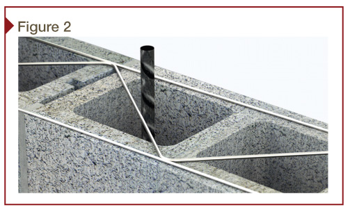
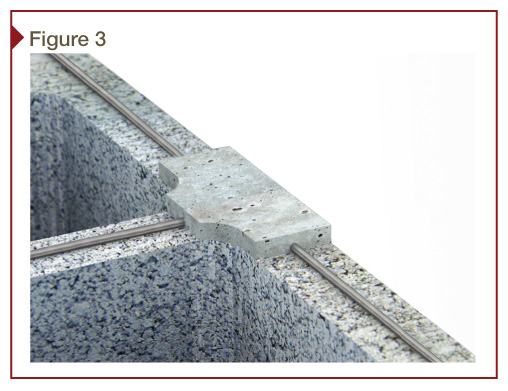
Ladder-shaped wire has perpendicular cross-rods butt-welded at 406-mm (16-in.) oc to the longitudinal wires. It is placed with cross-rods centered directly over the webs of the block (Figure 1). Placement of ladder wire in this manner eliminates obstructions caused by diagonal cross-rods common with the truss shape, especially where block cells are designed to contain vertical bars (Figure 2).
Grout flow
Another advantage of ladder-shaped wire is evident when grout is placed and consolidated. The absence of diagonal (truss) cross-wires improves the flow and consolidation of grout. Under Articles 3.43 B.4.d, the MSJC Code typically requires CMU block (i.e. hollow units) to be placed so vertical cells to be grouted are aligned. This provides an unobstructed path for grout flow. According to NCMA TEK 12-2B, “Because the diagonal cross wires may interfere with the placement of vertical reinforcing steel and grout, truss-type joint reinforcement should not be used in reinforced or grouted walls.”
Shrinkage control
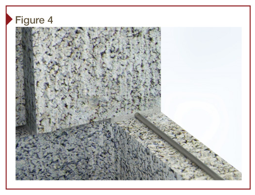
Ladder-shaped wire placed with cross-rods centered directly over block webs has yet another distinctive advantage. It positions butt-welded T-intersections of each longitudinal wire with cross-rods directly over T-intersections where block face shells meet each web. When laid in running bond pattern, two-cell block are placed with face shell mortar bedding only. Block webs are only mortar-bedded adjacent to vertically reinforced cells.
Face-shell mortar bedding will extrude at the webs when compressed during block placement, completely encapsulating the wire T-intersections, bonding the wire to the concrete masonry (Figure 3). Hence, the net result should be improved shrinkage crack control.
Standard 9-gauge versus heavy-duty 3/16
Besides its shape (i.e. truss or ladder), wire thickness is important in the placement process. The most common mortar joint thickness specified is 9.5 mm (3/8 in.). The largest diameter of wire allowed by Section 6.1.2.3 of MSJC Code would be half the mortar joint thickness—4.8 mm (3/16 in.). There are compelling reasons why the use of 9-gauge wire (i.e. 3.8 mm [0.148 in.) is more appropriate than a larger wire size that is heavy-duty (i.e. 4.8 mm [3/16 in.]).
Placement tolerances
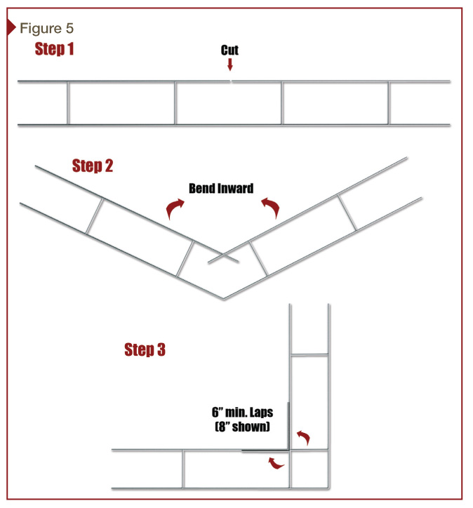
The MSJC Code tolerance for the placement of the mortar bed joint thickness is ± 3.2 mm (1/8 in.), as clarified in Article 3.3 F. 1. b. Therefore, a specified mortar joint of 9.5 mm (3/8 in.) would be allowed to vary from 12.7 to 6.4 mm (½ to ¼ in.) in thickness. With an as-built mortar joint thickness of ¼ to 3/8 inch, using heavy-duty 3/16-in. wire with hot-dip galvanized coating (per MSJC Code Section 6.1.4.2), would leave inadequate room for mortar cover to encapsulate the wire (Figure 4). Quite literally, block could be placed directly on the wire (i.e. block on wire on block).
In an article in the January 1995 issue of Masonry Construction magazine, “Selecting the Right Joint Reinforcement for the Job,” author Mario J. Catani states:
One compelling reason to use 9-gauge reinforcement is for fit and constructability. While the code allows joint reinforcement to have a diameter one half the mortar joint width, the tolerances allowed for units, joints and the wire itself can hinder the placement of large diameter reinforcement. Use it only when there is no other choice.
Forming corners
There is some debate regarding the merits of ordering factory prefabricated inside and outside corners versus field-forming them onsite. Since the MSJC Code does not distinguish the merits of either method (and, indeed, barely recognizes them), some interpretation is necessary.
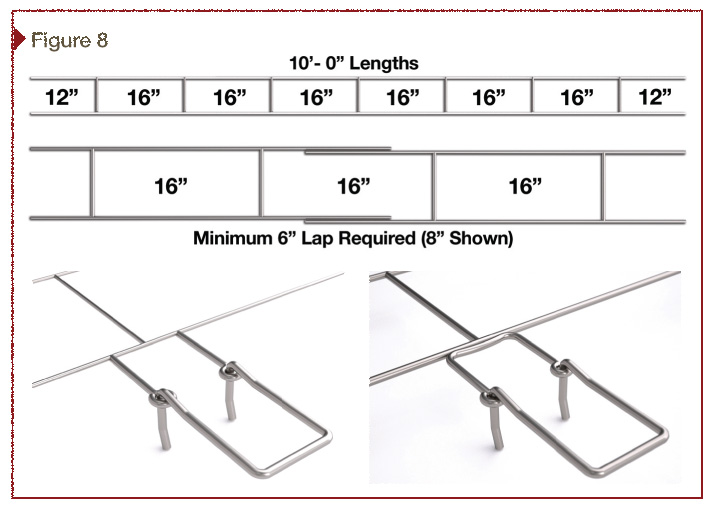
The standard for lapping wire reinforcement at any location is always the same—it requires a 152 mm (6 in.) minimum whether lapping straight 3.1-m (10-ft) sections one to another or where a straight section meets a corner (per Article 3.4 B.10.b). This requirement can also be applied to field-formed corners. The inside longitudinal wire can be cut and bent to form a 90-degree angle with a minimum of 152 mm (6 in.) of lap paralleling the newly formed inside longitudinal wire (Figure 5).
Factory-prefabricated corners may seem like the natural choice, but this can require additional lead time and cost for any size or configuration other than standard (8- or 12-in.) two-wire reinforcement. This is especially the case for custom-made adjustable hook and eye configurations.
Field-formed corners have many advantages. They meet all MSJC Code requirements and are easily formed to fit any corner condition. Each leg can be formed to fit to length, plus lapped in each direction off a corner, minimizing wasteful leftover from 3.1-m lengths that would otherwise head to a landfill. Field-formed corners eliminate lead time, cost less per lineal foot than factory-fabricated pieces, and only take a minute to cut and form to fit at the work station.
![Code approved mesh ties are safe, economical, and readily available. [CREDIT] Image courtesy Matt Fowler](http://www.constructionspecifier.com/wp-content/uploads/2014/05/CS_June_2014_HR-56.jpg)
Intersecting walls
MSJC Code allows prefabricated T-horizontal wire reinforcement sections where an interior non-loadbearing masonry wall intersects another for lateral support. However, this may not be the best selection. Such T-sections are typically embedded 406-mm (16-in.) on center during construction in the longitudinal wall, leaving the projecting leg of the T-section extending out approximately 609-mm (24 in.) until the intersecting wall is constructed.
Many masons will agree the exposed wire sections can be dangerous onsite, especially at eye height. Fortunately, MSJC Code also allows 6.3-mm (1/4-in.) mesh galvanized hardware cloth for interior non-loadbearing interesting walls (Figure 6). Additionally, MSJC Code allows Z-strap anchors for walls that intersect where shear transfer is desired. Projecting Z-straps share similar safety concerns with exposed T-sections. They only need to be used where the structural engineer indicates shear transfer. When applicable, mesh ties are typically the best choice. They are readily available, simple, and economical to install, and can be safely bent out of the way until the intersecting wall reaches their height.
Finish options
The two most common finishes for wire reinforcement are mill galvanized and hot-dip galvanized. The first category is allowed by the MSJC Code for most interior applications not in contact with moisture or high humidity. These standard mill galvanized finishes are produced through electro-galvanization—a process where a layer of zinc is bonded to steel when a current of electricity is run through a saline/zinc solution with a zinc anode and steel conductor. This process is undertaken when wire is in its raw state, before fabrication (i.e. cut and welded to shape) into wire reinforcement.
![This guide outlines joint reinforcement selection. [CREDIT] Image courtesy Masonry Institute of Michigan](http://www.constructionspecifier.com/wp-content/uploads/2014/05/CS_June_2014_HR-56-2.jpg)
Myriad advantages
Unfortunately, not all who design or specify wire reinforcement have kept pace with the shift to reinforced CMU. There are many pockets of the country where antiquated truss shape and/ or heavy-duty wire are still in use. Figure 7 reviews the advantages and disadvantages of ladder and truss shapes, along with standard 9-gauge versus heavy-duty wire reinforcement.
Additionally, ladder-shaped wire with 9-gauge side- and cross-rods has other advantages including lower production, packaging, and shipping costs. Lighter bundle weight reduces risk of back injury when they are handled on the jobsite. Ladder configuration also streamlines wire, rebar, and grout installation—this, in turn, enhances bricklayer productivity.
Specification
The following, and Figure 8, provides an example of the recommended wording for horizontal joint reinforcement in single and multi-wythe masonry walls:
PART 2 PRODUCTS
2.1 Masonry Reinforcing
A. Joint Reinforcement, General: ASTM A 961
1. Interior Walls: Mill galvanized, ASTM A 641 (0.10 ounces per square foot), carbon steel.
2. Exterior Walls: Hot-dip galvanized, ASTM A 153 Class B-2 (1.50 ounces per square foot) carbon steel.
3. Interior Walls Exposed to High Humidity: Hot dip galvanized, ASTM A 153 Class B-2 (1.50 ounces per square foot) carbon steel).
4. Wire Size and Side Rods: W1.7 or 0.148 inch diameter (9 gage).
5. Wire Size and Cross Rods: W1.7 or 0.148 inch diameter (9 gage).
6. Wire Size for Veneer Ties: W2.8 or 0.1875 inch diameter (3/16 inch).
7. Spacing for Cross Rods: 16 inches on center
8. Provide in lengths of 10 feet.
- B. Masonry Joint Reinforcement for Single-Wythe Masonry: Ladder type with single pair of side rods.
- C. Masonry Joint Reinforcement for Multi-Wythe Masonry: Ladder type with adjustable (two-piece) design, with separate double eye butt welded to side rod 16 inches on center. Double hook ties that engage eyes welded to reinforcement and resist movement perpendicular to wall. Hook tie length shall be sufficient to extend 1/2 inch minimum into outer face shell for hollow units and 1-1/2 inch minimum into solid units, but with a minimum 5/8 inch cover at outside face.
Conclusion
To control potential shrinkage cracking in a concrete masonry wall, it requires proper placement of control joints (CJs), along with placement of horizontal joint reinforcement. Horizontal joint reinforcement in a CMU wall does not prevent cracking, but controls it. Without it in a concrete masonry wall, shrinkage cracks may be visible and of a size penetrable by Mother Nature.
With 9-gauge ladder-shaped joint reinforcement in a concrete masonry wall, the longitudinal wire will go into tension as the concrete masonry is shrinking. Hence, an occasional microscopic crack should not be noticeable and would be less vulnerable to the elements. Use of truss-shaped wire does not meet code compliance and may negatively impact the integrity of a reinforced concrete masonry wall.
When it comes to masonry wire reinforcement, the old adage ‘less is more’ could not be any more true. Ladder-shaped wire, fabricated in 3.1-m (10-ft) long pieces with 9-gauge continuous side-rods and butt-welded 9-gauge cross-rods spaced 406-mm (16-in.) oc is the ideal choice for high-performance, economically designed CMU wall systems.
Dan Zechmeister, PE, FASTM, has been the executive director and structural services director of the Masonry Institute of Michigan (MIM) since 1986. He is an active member of ASTM, and a 2012 recipient of its International Award of Merit. Zechmeister also serves as a board member of the American Institute of Architects (AIA) Building Enclosure Council of Greater Detroit. He can be contacted at dan@masonryinfo.org.
Jeff Snyder, MBA, is the president of Masonpro Inc., a provider of specialty accessories to unit mason contractors. He has extensive field experience, including project managing for mason contractors in Texas and New Mexico. Snyder is a trustee with MIM, serving on its Generic Wall Design Committee. He can be contacted at jeff@masonpro.com.





While I believe horizontal joint reinforcement can be used to replace bond beam steel in cmu walls, can horizontal joint reinforcement also be used to replace ties around cmu column vertical steel bars. Your thoughts, Thanks is advance, Bill
Hello
Good day !
12 Years Gold Supplier Building & Construction Materials
Price will be sent to you regular when you reply us what size you need
Will you come to Canton fair ? Our Booth NO.14.4J17-18
Thanks
Andy
Email:admin@leeter.cn
Skype:leeter_happy@hotmail.com
My colleagues wanted AIA Document A305 earlier this week and discovered an online platform that hosts an online forms library . If people need AIA Document A305 too , here’s
https://goo.gl/wkFXQIIs joint re-I for enemy requires in non structural cmu walls that get poured solid amd have both vertical rebar as well as reinforced 4’ bond beam? Does anyone have a detail for a wall over 6’?