


by Sean M. O’Brien, PE, LEED AP, and David Artigas, PE
When properly implemented, field and laboratory testing of buildings and their systems and components can yield a wealth of useful information about construction quality, watertightness, durability, longevity, and other critical performance criteria.
Test results can help designers better evaluate ‘as-built conditions,’ understand any problems with the installation, and develop solutions appropriate to the specific problems that prompted the testing. When improperly implemented, however, testing can yield misleading results, lead designers to incorrect conclusions, and cause unnecessary expenses related to remedial work that may not really be warranted by the in-situ conditions.
In some cases, specifying inappropriate standards or performance criteria can create confusion or incite debate between the design and construction teams, especially in the event of a perceived failure. This article reviews some of the common test methods and procedures used in contemporary construction, with a focus on how the purpose of, and results from, these tests are often misunderstood.
Most important (but least asked) question
With dozens of industry organizations publishing thousands of test standards for buildings and building systems, there is almost always a quick answer to the questions: “What do I test and how do I test it?” However, the more important question, and one about which designers and contractors are often less sure, is “Why do I test?”
The answer to this question will almost always dictate the best method to use, the timing of the test, the pass/fail criteria, and sometimes whether it should be performed at all. In the case of poorly specified tests, the wrong tests are often performed ‘because it was in the specifications’ or ‘because the contractor owes us testing.’ Especially with fast-track construction projects, debates over testing are often brushed aside in favor of doing whatever the specification demands, regardless of the value of that testing.
In the authors’ experience, requiring designers to explain the reasoning behind their specified test methods or procedures can be an extremely useful exercise, either during the design process or as part of pre-construction activities. In the case of a designer having correctly specified test methods, the discussion can provide valuable information to the rest of the project team, giving everyone involved a better understanding of the reasons behind the testing. For improperly specified tests, the conversation can help avoid unnecessary testing and the resulting time/expense, as well as identify the correct test methods to determine the desired information.
Windows, doors, and curtain walls
Some of the most commonly tested building components are fenestration products—windows, doors, and curtain walls. For new construction, testing is most often specified as a quality control measure to ensure the installed system(s) meet the specified performance requirements for air and water penetration resistance.
The most common requirements are for testing in accordance with various American Architectural Manufacturers Association (AAMA) standards, depending on the system being evaluated. This requires the designer or specifier to know what type of system is specified as well as the relevant performance requirements to establish the appropriate test method.
There are different standards for different components, and some contain multiple test methods or options. For example, AAMA 501.1, Standard Test Method for Water Penetration of Windows, Curtain Walls, and Doors Using Dynamic Pressure, includes a method to test curtain fenestration for water penetration under dynamic wind pressure that requires a large fan—essentially, an airplane engine/propeller—and calibrated spray racks. There is also AAMA 501.2, Quality Assurance and Diagnostic Water Leakage Field Check of Installed Storefronts, Curtain Walls, and Sloped Glazing Systems, which is much easier to perform as it uses a simple handheld nozzle to spray along gaskets and joints. In this case, specifying testing per AAMA 501 is insufficient—the specific test method from that standard needs to be called out, as the two options vary greatly in scope and complexity.
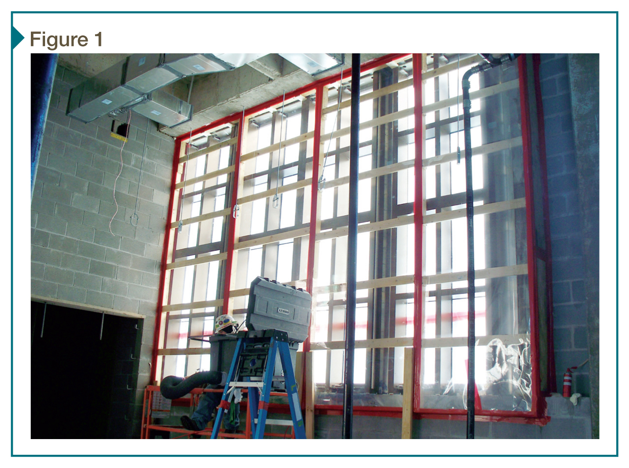
In previous versions of the AAMA 501 standard, a third option (501.3) was available to perform water leakage testing under static pressure differential (Figure 1). Despite this test being pulled from the standard and replaced by AAMA 503-02, Voluntary Specification for Field Testing of Newly Installed Storefronts, Curtain Walls, and Sloped Glazing Systems, references to the 501.3 method can still be found in specifications written today. This often results in confusion when the time comes to perform the tests.
AAMA 501.2 is intended as a field check for water leakage—a simple, economical method to verify the general quality of the curtain wall installation. For compliance with a specified level of air- and water-penetration resistance, AAMA 503 must be used. It is important to note 501.2 is solely intended for fixed glazing systems; the high nozzle pressure used would likely cause moderate to severe leakage on operable vents or window products due to the inherent limitations of seals and gaskets used in operable fenestration.
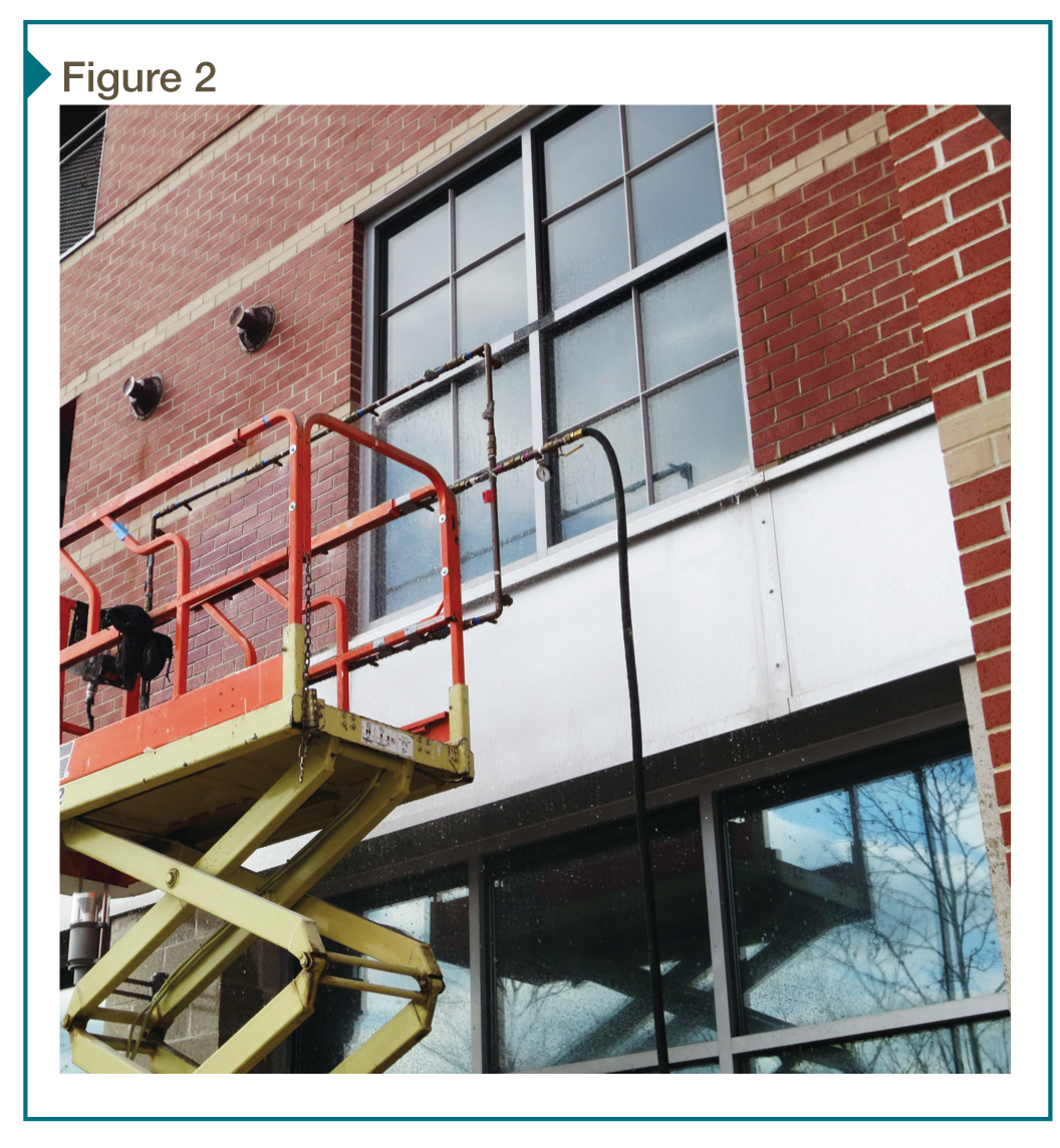
For testing window assemblies (both fixed and operable) for compliance with a specified air- and water-penetration, AAMA 502, Voluntary Specification for Field Testing of Newly Installed Fenestration Products, is typically specified. This involves building a chamber on the interior of the product to allow for negative interior air pressure and using a spray rack to wet the exterior of the window (Figure 2).
It is important to understand this test method has a specific definition of what constitutes a leak. For example, water on the sill members that does not pass the innermost projection of the window is not considered a leak, since it does not reach a point where it can damage interior finishes. This can come as a surprise to designers witnessing the test and seeing water on the sill, only to find out that by the standard’s strict definition, the window is considered to not have leaked. For this reason, some specifiers add their own language regarding the definition of leakage, but may have difficulty holding a manufacturer to this definition in the event of a dispute.
It is also important for designers to clearly specify the pass/fail criteria for windows. This information can be derived from the performance class (e.g. R, CW, or AW) and grade for the product being tested, but is often misinterpreted, leading to confusion during the test or attempts to hold installers/manufacturers to unrealistic or non-industry-standard performance criteria.
Another caveat of AAMA 502 (since the 2008 revision) as well as AAMA 503 is they only apply to newly installed fenestration products. The standards define ‘new’ as products installed before issuance of the certificate of occupancy for the building or products that have been installed for less than six months.
This recent development is often a source of debate, as this means a window installed for six months and one day, even in an unoccupied/incomplete building, is no longer subject to AAMA 502 and therefore cannot be tested for compliance with the manufacturer’s stated performance criteria. In simpler terms, the manufacturer of the window is only held to its stated performance criteria for six months. For older products, AAMA 511, Voluntary Guideline for Forensic Water Penetration Testing of Fenestration Products, contains diagnostic procedures for identifying known leaks, but is not specifically intended to evaluate in-situ performance of non-leaking windows.
When specifying testing, it is important to make the distinction between test specifications, standard test methods, and testing guides. Each of these types of documents is used for a different, but often similar, purpose. Standard test methods, such as ASTM E1105, Standard Test Method for Field Determination of Water Penetration of Installed Exterior Windows, Skylights, Doors, and Curtain Walls, by Uniform or Cyclic Static Air Pressure Difference, contains specific information on how to physically test these various components, what equipment to use, and related information.
Test specifications, such as AAMA 502, provide procedural information on the testing, the relevance/applicability of the testing, and related administrative information, and typically reference standard test methods (e.g. ASTM E1105) for the physical test procedures.
Finally, testing guides, such as ASTM E2128, Standard Guide for Evaluating Water Leakage of Building Walls, are usually more general in nature and cover a wide range of components and procedures rather than focus on one specific area of the building enclosure. Similar to test specifications, these guides include procedural/administrative requirements and reference standard test methods for the actual testing procedures. Due to their non-specific nature, including ‘compliance’ with a testing guide such as ASTM E2128 as a specification requirement is likely to result in confusion, as it can be interpreted in many ways for many different components. A testing specification and pass/fail criteria must be clearly identified in the contract documents.
Roofing assemblies
Leakage from roofing systems, especially in the case of low-slope assemblies, can result in significant interior damage when left unchecked. There are many different methods for testing roofs, but not all are compatible with all assembly types. Understanding which methods can be used for which systems is key to specifying the appropriate test, whether as part of a specification for quality control in new installations or as part of remedial/troubleshooting efforts.
In this article, the authors focus on large-scale testing of roof areas, as opposed to smaller-scale testing of specific detail conditions (which is most often done using spray racks/nozzles or localized flood testing). As discussed, the roof’s configuration, as well as the specific membrane type, must be considered when specifying a test method.
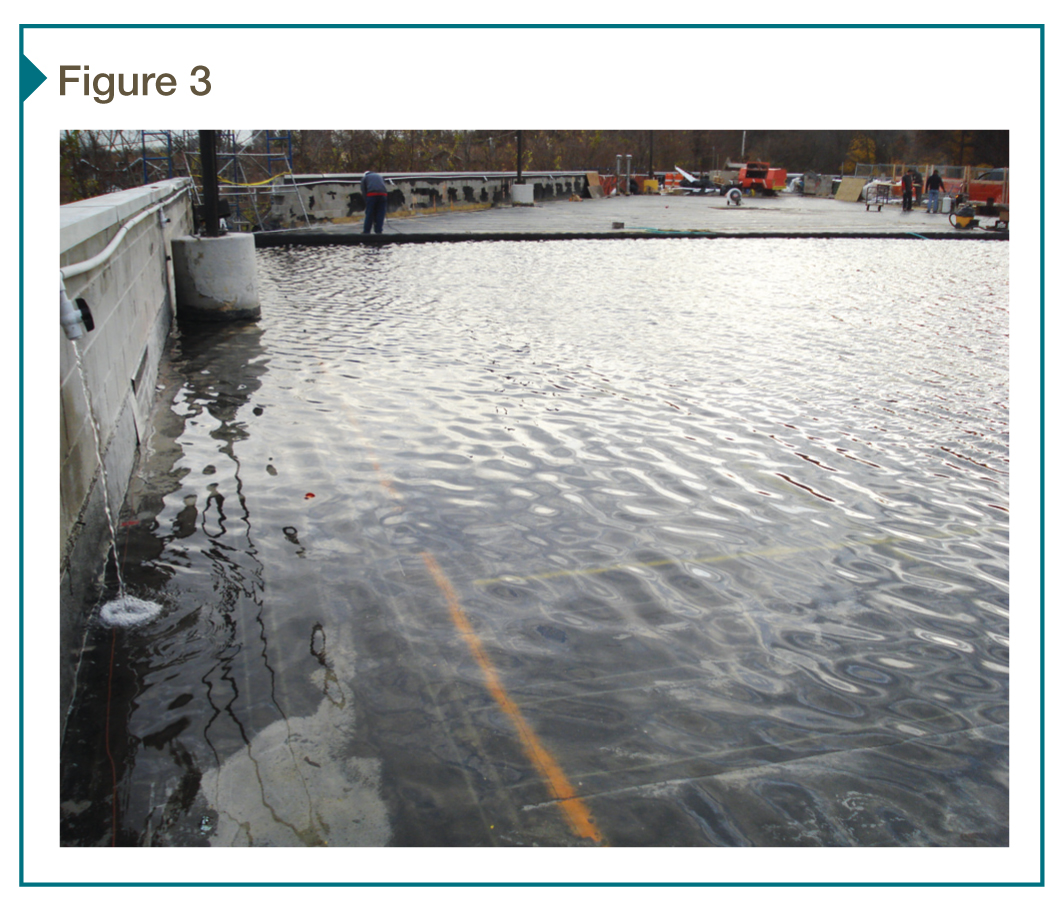
The most obvious method of testing a roof—flooding it with water—can be effective in some cases, but extremely damaging in others. Flood-testing is best-suited to inverted roof membrane assemblies (IRMAs) where the membrane is installed directly over the structural deck, with insulation and ballast or other overburden above. In those cases, the testing is performed once the membrane and flashings are complete but prior to the installation of any overburden (Figure 3).
For this test, which is standardized in ASTM D5957, Standard Guide for Flood Testing Horizontal Waterproofing Installations, water is ponded over the system for a period of 24 to 72 hours, during which time the interior is reviewed for leaks. The depth of water must be reviewed to ensure the structural capacity of the roof is not exceeded, as every inch of water adds approximately 0.24 kPa (5 psf) of load. This can be challenging on large or complex roofs, where the deck slope may require compartmentalizing the test into smaller areas. Any leaks resulting from this test are likely to produce only localized damage which gets repaired along with the leaking component(s).
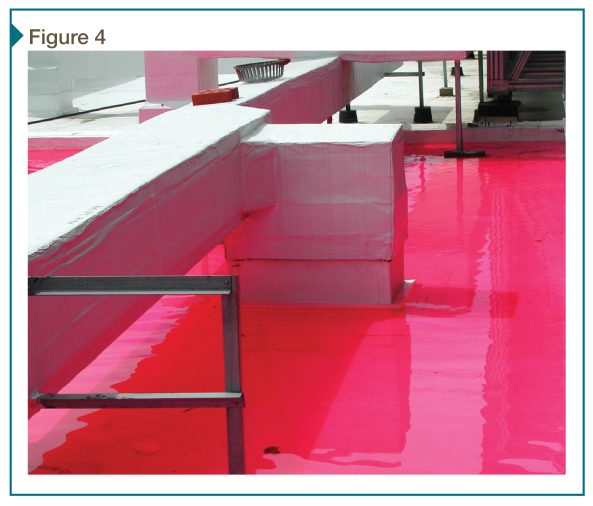
This test procedure is not appropriate for traditional ‘membrane-over-insulation’ roof systems, since leakage through the membrane may wet (and necessitate the replacement of) large areas of roof insulation. Especially in the case of a concrete roof deck, leakage through the membrane could go unnoticed or travel far from the original location as the deck retains the water, allowing large areas of insulation to become damaged and making it difficult to determine the leak’s source. These risks can be reduced by flooding only small areas at a time (limiting the amount of water that could enter the roof), in which case the water can be dyed to provide confirmation of leak sources if multiple areas are flooded in sequence (Figure 4).
There are several test methods available for traditional insulated roofing systems that do not carry the same risk of large-scale damage. These methods typically rely on specialized equipment to detect wet insulation below the membrane. Infrared (IR) thermography uses an infrared camera that visualizes temperature differences on surfaces by measuring and processing emitted radiation.
For an insulated roof, wet insulation will tend to retain more heat and cool slower than dry insulation. Since moisture from roof leaks is often trapped in the system for an extended period, scanning of a roof with suspected or known leaks shortly after the sun has set can help identify areas of wet insulation.
The IR camera measures the surface temperature of the membrane, so this method cannot be used on ballasted roofs since the ballast (e.g. gravel) will cool off uniformly and mask any small temperature differences on the membrane below. Similarly, testing on a windy day may yield misleading results as airflow over the membrane surface may even out temperature differences or cause the wet areas to cool off to the same temperature as the surroundings before the scan is made.
IR scanning of a roof is relatively efficient since large roof areas can be surveyed relatively quickly (some companies even offer aerial surveys, which can be economical for very large, open roof areas). A second method, often referred to as electrical capacitance/impedance (EC) testing, uses handheld or rolling (push-cart) equipment that sends electrical pulses into the roof system and measures the insulation’s ability to retain electrical charge. Wet areas will tend to hold a charge for less time than dry, allowing for relative comparison between areas. Similar to infrared, this method requires an exposed roof membrane since the scanner needs to be in close proximity to the insulation to be effective. For this method to be effective, the roof membrane needs to be non-conductive, making it ineffective on most ethylene propylene diene monomer (EPDM) assemblies or on membranes with metallized reflective coatings. For both of these methods, secondary verification (i.e. roof probes) of suspected wet materials should always be specified to confirm the efficacy of the test for the specific application.
A more recently developed test method uses specialized equipment to pinpoint specific defects in the membrane. In this method, a potential difference is created between the wetted roof surface and the grounded roof deck. Any breaches in the membrane create, in effect, a short circuit in the system which can be detected using specialized equipment.
This method can be used on both traditional and IRMA systems, but—similar to EC testing—the roof membrane must be nonconductive for the method to work. For new construction, especially on traditional roof systems, a grounding screen can be added below the membrane or cover board to provide more positive leak detection and become part of a permanently installed leak detection system. This type of system can be especially beneficial for vegetated roofing assemblies where the often significant amount of overburden can make locating leakage sites extremely difficult.
Brick masonry and exterior walls
Brick masonry has been a common building material in the United States since the colonial period, and mass masonry walls continued to be built through the first half of the 20th century. While the basic process of brick manufacturing has not changed much, modern technology allows the creation of brick typically much stronger and has greater uniformity of properties than historic brick. Historic lime mortars typically are softer and more permeable than modern cement mortars, which allows them to absorb greater stress within the wall from expansion and contraction or enables the wall greater capacity to ‘breathe.’
Concerns with historic masonry fall under two, often related, headings: the masonry’s structural capacity and durability. While it certainly is true modern masonry manufactured and constructed to meet modern standards should result in durable construction, it is not always necessary to hold historic masonry to these same modern standards, as the historic materials often have more than the necessary capacity to provide a long service life with good performance. Also, certain properties being lesser than modern standards may prove beneficial to performance.
The International Building Code (IBC) now has requirements for masonry properties such as compressive strength and performance in shear, though that was not always the case. Current codes are written for current construction, and do not always include previsions for how historic construction ‘works’ structurally. The International Existing Building Code (IEBC) includes provisions that allow historic buildings to remain, or repairs to occur, using original or like materials, but the structural engineer and code officials must still evaluate the structure’s capacity to withstand its loads and remain safe.
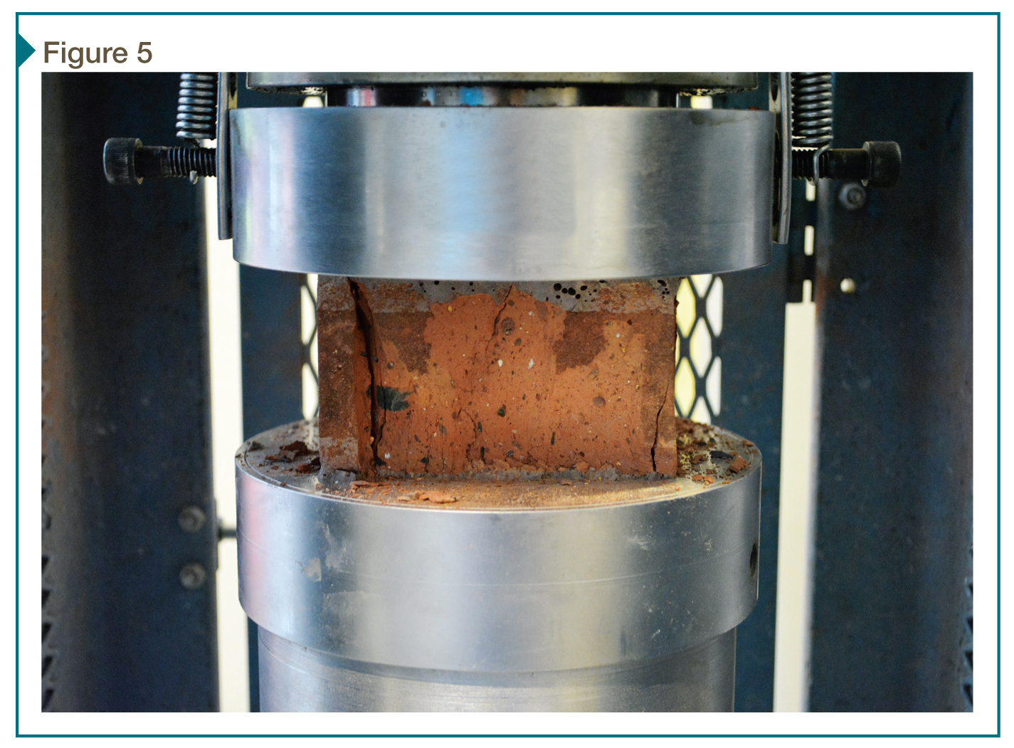
Structural engineers can use both non-destructive and destructive methods to determine masonry’s strength and ability to withstand stresses (Figure 5). It is important to specify testing appropriate to both the structure being evaluated and the goal of the evaluation. While a historic mass masonry wall may not meet the letter of the current code requirements, it may have capacity that exceeds its in-service loads with an acceptable factor of safety comparable to the code. That said, one concern with mass unreinforced masonry is it typically does not perform well during seismic events. In areas of higher seismic activity, greater care must be exercised in its evaluation.
Current requirements for energy efficiency mandate the building enclosure to have a specified resistance to heat transfer. While mass masonry walls typically have a lower R-value than modern insulated wall assemblies, they have an advantage—their bulk provides thermal mass unmatched by newer assemblies comprising several thinner layers of different materials sandwiched together. This thermal mass allows the wall to absorb and dissipate heat more slowly than modern walls, slowing the interior of the building’s reaction to changes in the exterior temperature and reducing the need for supplemental heating or cooling.
Changes to the thermal properties of a mass masonry wall, such as adding insulation to the interior, or significantly increasing the interior moisture load, may affect brick performance. Uninsulated historic masonry typically allows moisture to move through the wall (i.e. ‘breathe’) while remaining above the dewpoint, since the interior heat warms the wall.
The addition of interior insulation will reduce the wall’s temperature during the colder months. Water absorbed by the brick’s exterior wythe may go through freeze-thaw cycling as a result of the wall now being colder, and interior moisture that migrates through the wall assembly may condense on the inboard side of the masonry wall, because this side of the wall now is on the ‘cold side’ of the insulation.
Historic masonry may have two advantages that will reduce the likelihood of these two events occurring.
1. Historic brick typically is more porous than modern brick. This greater porosity may allow the brick to ‘drain’ rainwater more quickly than modern brick, and the larger pores may allow the absorbed water more room to expand without causing damage.
2. Historic lime mortars are more absorptive and permeable than modern mortars, and these properties may allow the mortar to wick water rather than having it remain on the wall.
However, it must be stressed the reaction of mass masonry to the installation of interior insulation is still a topic of study among engineers and preservationists. Further, there are currently no established guidelines for insulating walls, only various opinions on the matter.
Many designers of renovation projects may equate strength with durability and specify masonry testing with this thought in mind. Great care must be exercised when considering insulating mass masonry walls, and testing of the masonry’s porosity, absorption, permeability, expansion, and relative strength (both of brick and of mortar) should be performed. Additionally, laboratory testing and evaluation to determine the relative durability of the brick, as well as its resistance to freeze-thaw damage, are a crucial part of this kind of study.
It is also critical to evaluate test results in light of numerous factors, such as the type of building/occupancy, building use, and general quality of the surrounding construction. If a sampling of brick test as SW grade (suitable for severe weathering per ASTM C216, Standard Specification for Facing Brick [Solid Masonry Units Made from Clay or Shale]) that does not necessarily mean the wall assembly in question has the level of durability required for the specific application. SW brick on a large, clear wall area will likely provide suitable performance, but the same brick installed in a shaded location (i.e. minimal drying) below a window that experiences leakage (i.e. excessive wetting) may undergo premature degradation regardless of the brick grading.
The most important question to ask when evaluating a historic masonry building is: “How has it performed thus far?” If the building shows no obvious signs of distress after several decades or even centuries of use, its testing and evaluation must begin from a position of “How does it work?” as opposed to one of “Does it meet the code requirements for modern construction?”
This understanding will include site observations and possibly onsite or laboratory testing, and research into historic construction methods and materials. Ultimately, this approach to evaluating historic masonry may lead to a more efficient and lower cost project that also can maintain the building’s character. Regardless of testing, designers who take this approach much understand when the use of the building or other characteristics of the enclosure are changed as part of renovations, the prior performance of the building may not be a suitable predictor of long-term durability.
From a water penetration standpoint, there are many different test methods available for masonry walls, but not all provide useful information. For example, ASTM C1601, Standard Test Method for Field Determination of Water Penetration of Masonry Wall Surfaces, determines water penetration at the surface of a masonry wall, but does not provide any information on how much water actually leaks to the interior (as opposed to water that is absorbed and stored by the masonry). Similarly, RILEM tubes can be used to provide relatively quick evaluations of the water absorption rate of a masonry wall.1
ASTM E514, Standard Test Method for Water Penetration and Leakage Through Masonry, provides for measurement of the actual amount of water penetrating the full thickness of the masonry, but this is a lab test not applicable to field conditions (although it is often specified—incorrectly—by designers evaluating existing masonry buildings). Field surface absorption tests may have limited use in qualitatively evaluating the change in absorption that results from installing a penetrating sealer, but are typically of little to no use in evaluating water leakage.
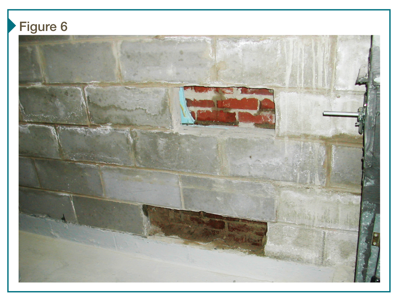
Neither of these tests will be of practical value for masonry cavity wall construction, where any water penetrating the exterior façade is collected in a drainage cavity and wept out of the system (Figure 6). Water leakage through a masonry cavity wall is more likely the result of a breach in the water-resistive barrier (WRB) behind the masonry, since masonry veneer systems are expected to allow water into the drainage cavity.
The authors have generally found the general guidelines from ASTM E2128, Standard Guide for Evaluating Water Leakage of Building Walls—as opposed to one specific standard test method—are helpful in establishing the right combination of testing and inspection to diagnose water leakage through masonry walls.
Air barrier systems
As far as building testing goes, the testing of air barrier systems is a relatively recent development.2 Just as with window and curtain wall testing, there are multiple test standards and guides for testing air barrier systems in both the lab and the field. One of the first points of confusion is the definition of an air barrier—a system of interconnected components including walls, windows, curtain walls, and roofs that act together to prevent uncontrolled airflow into and out of the building. While air barrier testing is often thought of as testing a wall air barrier membrane (one component of the system), it can encompass everything from single materials to the entire building enclosure.

Testing of actual materials, such as sheet- and fluid-applied membranes, is performed in the laboratory due to the very small quantity of air leakage being measured and the high degree of accuracy required in the measurement. Air barrier products are required by most codes to allow no more than 0.02 L/s.m2 @ 75 Pa (0.004 cfm/sf at a pressure differential of 0.3 in. of water). In reality, most sheet membranes (such as self-adhered rubberized asphalt products) exceed this criteria by an order of magnitude or greater—much too low to be reliably measured in the field.
Air barrier assemblies—essentially, air barrier materials in an as-built condition that includes laps, seams, and penetrations—can be tested in either the lab or the field. Laboratory testing per ASTM E2357, Standard Test Method for Determining Air Leakage of Air Barrier Assemblies, provides an air leakage rate for a pre-defined arrangement of air barrier products, penetrations, and a window opening (but not the window itself—an oft-overlooked element of the air barrier system).
While primarily a laboratory test used by air barrier manufacturers to demonstrate their products’ performance and code compliance, the method can also be applied to field-installed mockups. However, applying this test in the field is not as simple as installing a chamber on the interior and testing the exterior. Air leakage through the perimeter of a sample area (e.g. through a concrete block or stud wall perpendicular to the interior-exterior direction) is often impossible to isolate, and due to the relatively low leakage rates being measured, even a small amount of extraneous leakage can create a false negative test result. Using this general chamber testing approach on a qualitative basis is simpler and often more effective, since telling a contractor that the test result was 0.25 L/s.m2 (0.05 cfm/sf)—in other words, a failure—does not provide the same level of usefulness as telling them there were leaks at one membrane seam and two brick ties that need to be repaired.
Specifications for field-installed air barrier assemblies often include testing of the window as part of the assembly. While this makes sense from a practical standpoint (i.e. the connection to the actual window system is a critical transition in the air barrier), there are limitations to this test. From a practical standpoint, mockup testing of air barrier assemblies typically happens at the beginning of a project, often long before the windows are delivered to the site (or in some cases, before specific window products are even selected). Testing of the assembly with a ‘dummy window’ in place is possible, but results can be misleading since the actual connection is unlikely to be the same as what is intended for the project windows.
In cases where the dummy window is put in temporarily with sealants and sprayed-applied foam insulation, the actual leakage rate may be much lower than what will occur when the project windows are installed, giving a false positive result for the test. In the case of the project windows being available at the time of testing, the specification of pass/fail criteria for the air barrier assembly test becomes more important. The performance criteria for air barrier assemblies are based on a window perimeter being included, but not the window itself. Since most windows will experience significantly higher leakage (on an area basis) than air barrier materials and assemblies, leakage through the window may far exceed the air barrier assembly leakage criteria, even if the assembly itself, minus the window, would pass on its own. For this reason, it is important to clearly specify how and if the window is to be included in the test, and, if so, some increase in allowable air leakage needs to be included to avoid requiring a result which is not attainable in the field.
The third type of air barrier testing is whole-building testing, using blower door or similar equipment and ASTM E779, Standard Test Method for Determining Air Leakage Rate by Fan Pressurization, procedures to measure overall air leakage through the entire building—including all walls, roofs, and windows. Different codes and standards require different overall leakage rates, but 0.02 L/s.m2 @ 75 Pa (0.4 cfm/sf at 0.3 in. of water) is typical for most building and energy codes.
While this test provides a single number to describe air leakage that can be easily compared to other buildings, it has many limitations that must be considered before requiring a certain level of whole-building performance. The first major issue is at the time when the air barrier is substantially complete to the point where testing can be performed, it is also likely to be concealed by cladding and other materials that can make the detection (using IR thermography or tracer smoke) and repair difficult or impossible.
Second, the testing itself can be difficult to perform, especially on large/more complex buildings, due to the need for multiple fan systems that must all be linked together for measurement or adjustment. In tall buildings, internal fans may be needed to equalize pressure differentials over the height of the building. While most testing firms can easily come to a site and perform standard window or curtain wall tests, large-scale testing of whole buildings requires specialized equipment and a fair degree of experience and expertise to successfully execute.
Lastly, there is some debate over what is achievable in terms of air leakage through whole buildings. A designer can certainly specify the overall leakage rate needs to be 0.5 L/s.m2 (0.1 cfm/sf), but achieving that level of airtightness requires an exceptionally well-designed air barrier, as well as carefully planned execution of the construction.
This is a common mistake with all types of air barrier testing—specifying a high level of airtightness without providing the corresponding design detailing is a futile effort. As mentioned, once the building is physically ready to be tested, it is often far too late to practically implement repairs, which brings up the difficult question of “What do we do now that we failed the test?” While the industry is still working on answering that question, specifiers can help avoid problems by specifying reasonable levels of airtightness appropriate for the building design.
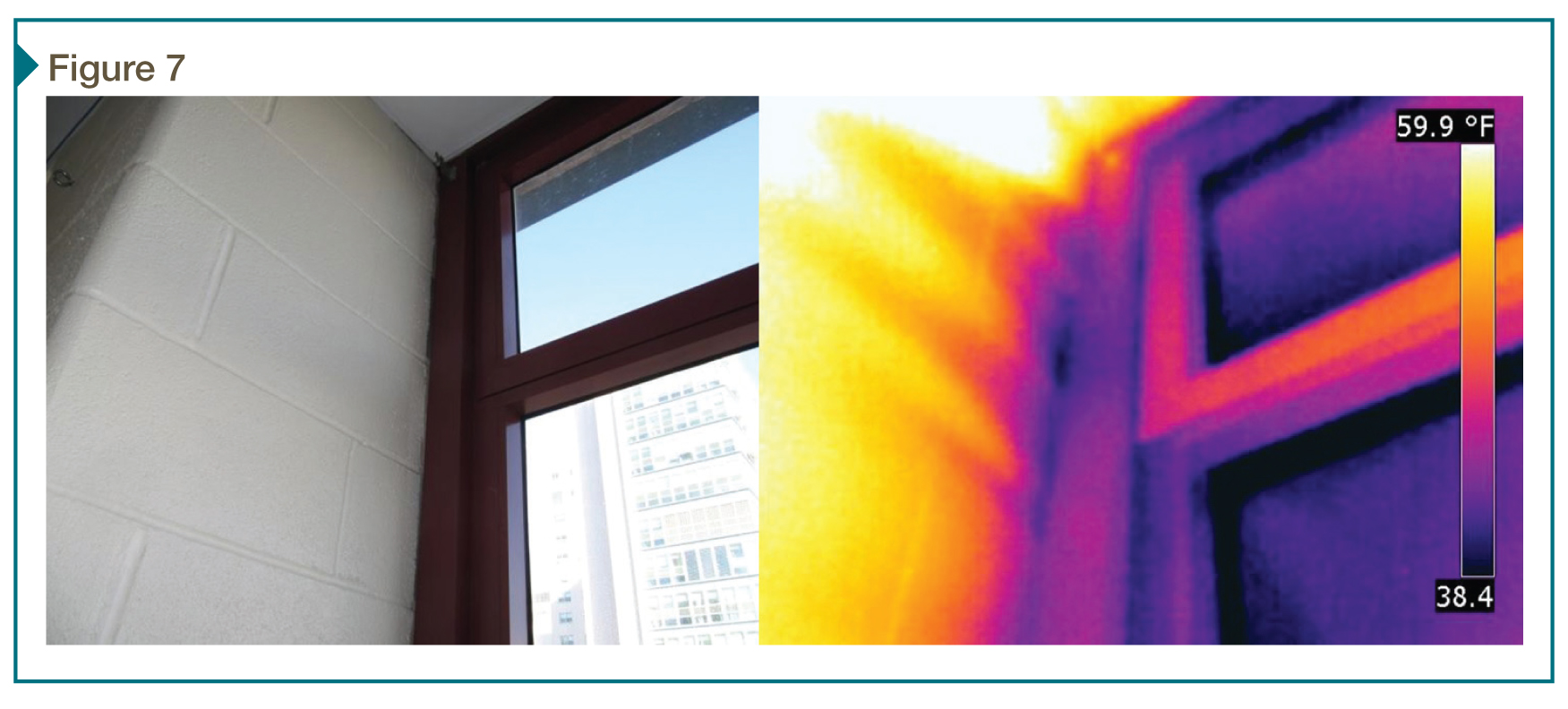
As with the other previously described tests, visualization techniques such as infrared thermography and tracer smoke can be used to take advantage of the pressure differential created during a whole building test and qualitatively identify air leakage sites (Figure 7).
Conclusion
While the wide variety of available testing standards means there is almost always a standard for the designer’s specific need, finding the right standard can be difficult when one does not have a firm understanding of the actual goals. Designers and specifiers should first evaluate the question of ‘why’ when it comes to testing, as the answer will typically guide them to the correct test method to follow.
Specifying both the appropriate testing method and the appropriate pass/fail criteria are necessary to provide meaningful test results and avoid the time and expense of unnecessary testing or inappropriate testing which leads to ambiguous results. A little more time spent researching test methods during the design phase and specifying appropriate methods and performance criteria can go a long way toward reducing confusion and disputes during the construction process in the field.
Notes
1 For more on RILEM tubes, see The Construction Specifier articles, “Testing the Test: Water Absorption with RILEM Tubes,” by Adrian Gerard Saldanha and Doris E. Eichburg, and “Durable Waterproofing for Concrete Masonry Walls: Redundancy Required,” by Robert M. Chamra and Beth Anne Feero in the August 2013 and July 2014 issues. (back to top)
2 For more on air barriers, see the article “Wind Load and Air Barrier Performance Levels,” by Maria Spinu, Ben Meyer, and Andrew Miles, in the July 2014 issue. (back to top)
Sean M. O’Brien, PE, LEED AP, is an associate principal at the national engineering firm Simpson Gumpertz & Heger (SGH), specializing in building science and building enclosure design and analysis. He is involved in both investigation/forensic and new design projects. O’Brien is a member of the American Society of Heating, Refrigerating, and Air-conditioning Engineers (ASHRAE), co-chair of the New York City Building Enclosure Council (BEC-NY), and a frequent speaker and author on topics ranging from building enclosure design to energy efficiency. He can be reached at smobrien@sgh.com.
David Artigas, PE, is senior staff I–building technology at SGH, specializing in building enclosure design and investigation, building science, and historic preservation. He can be reached at djartigas@sgh.com.

