

by Richard Filloramo, B.S. Arch, A.S. CT, and Chris Bupp
Masonry materials and wall assemblies, with their inherent thermal mass characteristics, provide designers with many options to achieve efficient designs. Architects and engineers have to make new decisions to reduce their projects’ energy consumption, requiring close collaboration and coordination with building and energy codes, along with construction documents.
The most significant code changes include increased R-values for non-mass opaque walls (e.g. cold-formed metal framing), requirement options for continuous insulation (ci), a need for continuous air barriers, R-value reductions for thermal bridging, and three paths for building energy design.
The 2015 International Building Code (IBC), in Chapter 13 (“Energy Efficiency”) states buildings shall be designed in accordance with the 2015 International Energy Conservation Code (IECC). The latter code’s Chapter 5 (“Commercial Energy Efficiency”) enables designers to use either IECC or American Society of Heating, Refrigerating, and Air-conditioning Engineers (ASHRAE) 90.1-2013, Energy Standards for Buildings except Low-Rise Residential Buildings.
This article examines examples of energy design using ASHRAE 90.1-2013, Section 5 (“Building Envelope”), and also notes requirements from ASHRAE 90.1-2010 (per the 2012 IBC and IECC). Designers may select ASHRAE 90.1 over IECC Chapter 5 because it provides a more in-depth, comprehensive, and complete approach to building energy design.
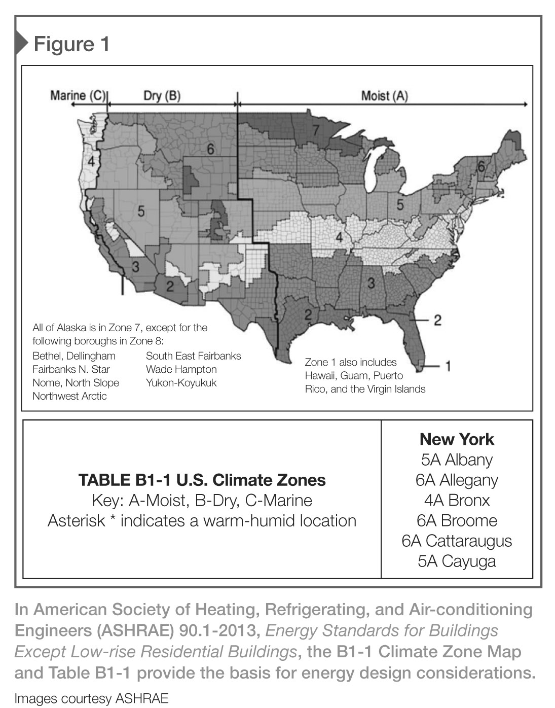
First, a designer must determine the climate zone for the building location by using the ASHRAE appendix Figure B1-1 map and tables depicted in Figure 1. For example, all of Connecticut is in Climate Zone 5, while New York encompasses three Climate Zones—Table B1-1 indicates the appropriate zone for the various towns, cities, and counties.
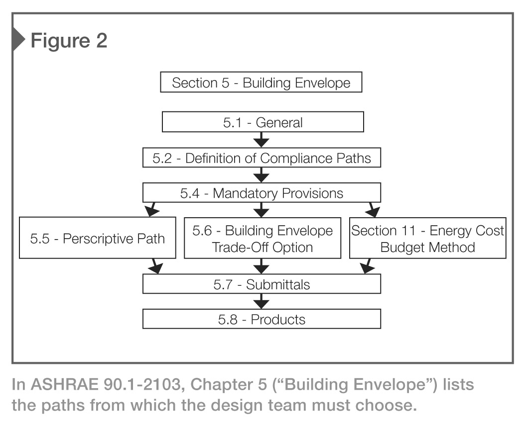
Next, the architect will select a compliance path based on the climate zone, space conditioning category (ASHRAE 5.1.2) and class of construction from ASHRAE Section 5.2 (“Compliance Paths”), as shown in Figure 2. The building envelope must comply with Sections 5.1, 5.4, 5.7, and 5.8, along with either:
? Section 5.5 (“Prescriptive Building Design Option”), provided the fenestration area does not exceed the maximum allowed in Section 5.5.4.2 (40 percent in ASHRAE 2012); or
? Section 5.6 (“Building Envelope Trade-off Option”).
Projects may also use Energy Cost Budget Methods, Section 11, as described in ASHRAE 90.1, Section 5.2.2. This article focuses on the first option—the prescriptive path (Section 5.5)—and also discuss Section 5.4.3 (“Air Leakage and Continuous Air Barrier Requirements”).
The prescriptive path
While larger commercial, institutional, and municipal buildings may use some form of energy modeling (Section 5.6 or Section 11), the examples shown using the prescriptive path demonstrate basic compliance with the code and assist at understanding assembly R-values for various building envelope wall systems. The prescriptive path method provides an efficient means to establish the required insulation in a wall that can be used in a final design or in a preliminary study.
ASHRAE 90.1, Section 5.5 provides building envelope design tables for all climate zones for either non-residential or residential construction. (The latter includes dwelling units, hotel/motel guest rooms, dormitories, nursing homes, patient rooms in hospitals, lodging houses, fraternity/sorority houses, hostels, prisons, and fire stations.1)
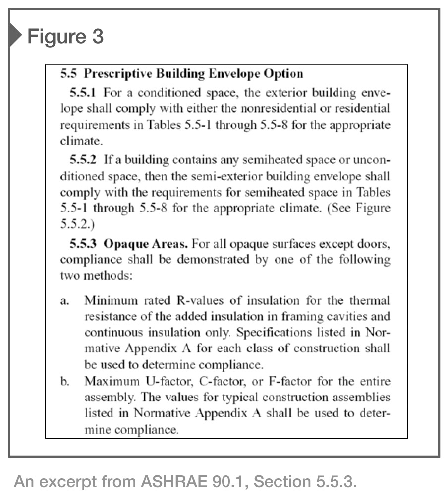
To comply with the prescriptive path for Opaque Areas (Section 5.5.3) a designer may select from one of the two following methods:
? Method A: minimum R-value insulation requirements; or
? Method B: maximum U-factor (or R-value) for the entire assembly (Figure 3).
The second method is a more efficient means to configure a masonry wall assembly.
Building envelope basics
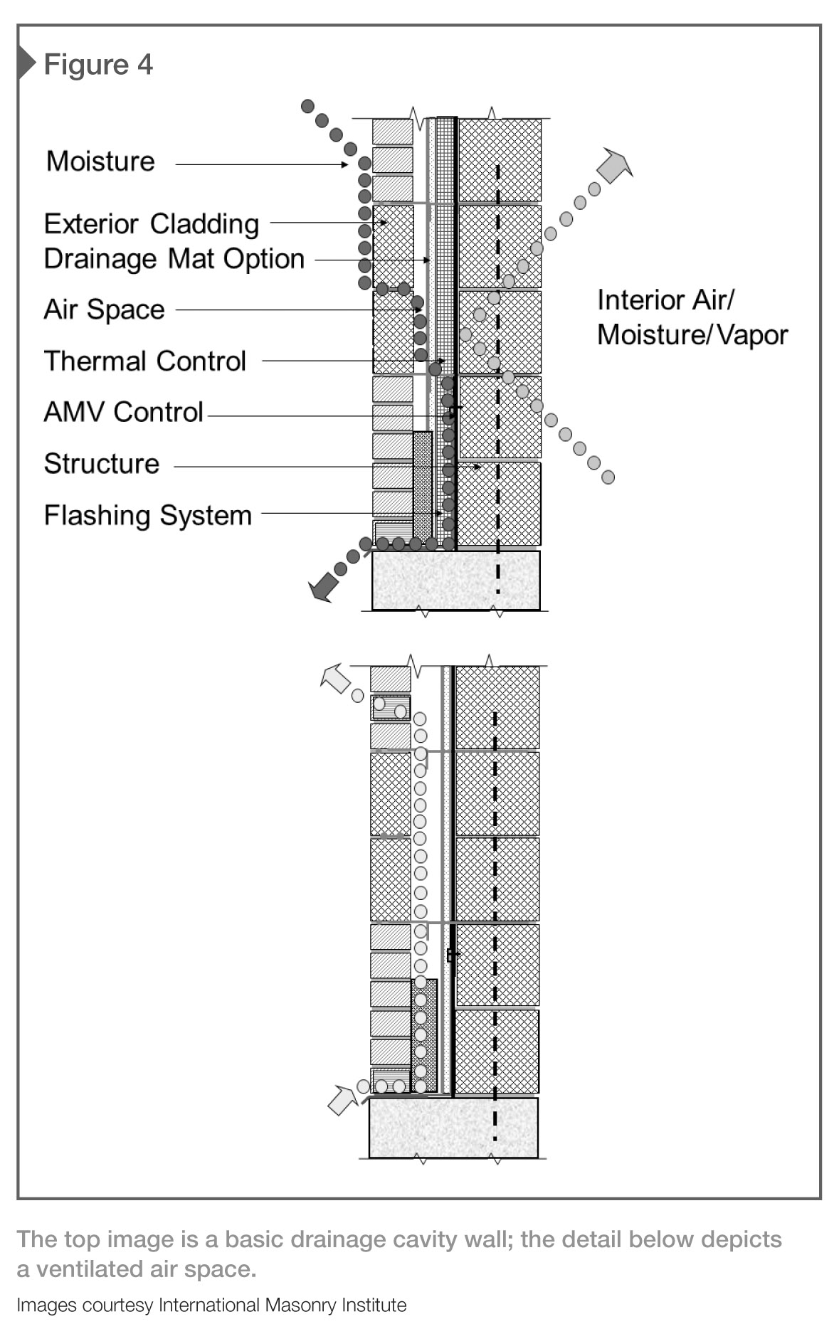
An essential component of wall design—masonry or otherwise—is drainage capability and ventilation air space. IBC Chapter 14 (“Exterior Walls”) requires the exterior wall envelope be designed and constructed in such a manner as to prevent the accumulation of water within the wall assembly by providing a water-resistive barrier behind the exterior veneer, and a means for draining water that enters the assembly to the exterior. While there are exceptions, this requirement is essential to successful design.
Ventilated air space is also essential to keep the wall components dry, which prevents deterioration of wall components and water infiltration. Providing a sufficient air space in accordance with industry standards has become more difficult as new energy requirements can increase insulation thickness—owners are apprehensive to allow thicker walls that will encroach on the net interior building area.
The 2015 IBC references the Masonry Standards Joint Committee (MSJC)’s Building Code Requirements for Masonry Structures (i.e. The Masonry Society [TMS] 402-13/American Concrete Institute [ACI] 530-13/American Society of Civil Engineers [ASCE] 5-13) and Specifications for Masonry Structures (TMS 602-13/ACI 530.1-13/ASCE 6-13). In Chapter 12 (“Veneers”), Sections 12.2.2.6.2, 12.2.2.7.4, 12.2.2.8.2, and 6.2.2.8 states:
A 1-in. (25.4 mm) minimum air space shall be specified.
However, this is a code minimum and not recommended. Standard construction tolerance for the veneer and backup of ± 6 mm (¼ in.) variation from plumb can leave a resulting 12-mm (½-in.) air space, which is unacceptable. Industry organizations such as the International Masonry Institute (IMI), Brick Industry Association (BIA), and National Concrete Masonry Association (NCMA) recommend a 50-mm (2-in.) minimum air space. With these new increased requirements for higher R-values and sometimes thicker insulation, a 38-mm (1 ½-in.) air space would be sufficient. If air spaces are smaller, it may be advisable to provide continuous, full-height drainage mat in the wall cavity to assist with drainage and air flow and prevent mortar bridging (Figure 4).
It should also be noted MSJC sets the maximum cavity space at 114 mm (4 ½ in.) based on prescriptive design. Cavity spaces exceeding this size are acceptable, provided engineering calculations are provided for the masonry veneer ties. Recently, newer and stronger masonry ties, anchors, and fasteners have been developed that provide sufficient strength for wider cavities.
Understanding the prescriptive path
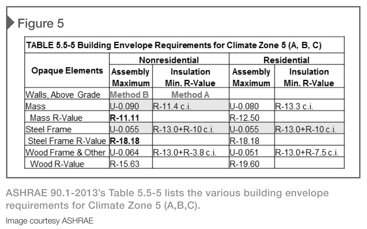
An example of ASHRAE Table 5.5.5 for Building Envelope requirements in Zone 5 is shown in Figure 5. A masonry mass wall (masonry veneer and concrete masonry unit [CMU] backup), non-residential, under Method B (first column), would require an assembly U-factor of U-0.090—this equals R- 11.11(R=1/U). It should be noted there was no increase in the required R-value for mass walls from the R-11.11 in 2012 IBC/IECC/ ASHRAE 2010).
The same mass wall under Method A (second column) would require continuous insulation with a minimum R-value of R-11.4. A steel-framed wall (masonry veneer and steel stud backup) under Method B requires an assembly U-factor of U-0.055—this equals R-18.18. It should be noted this is a significant increase from R-15.63 required in the 2012 IBC/IECC/ASHRAE 2010). The same stud wall under Method A would require R-13 insulation in the stud space and R-10 continuous insulation (R-13 / R-7.5 ci in 2012 IBC/IECC ASHRAE 2010).
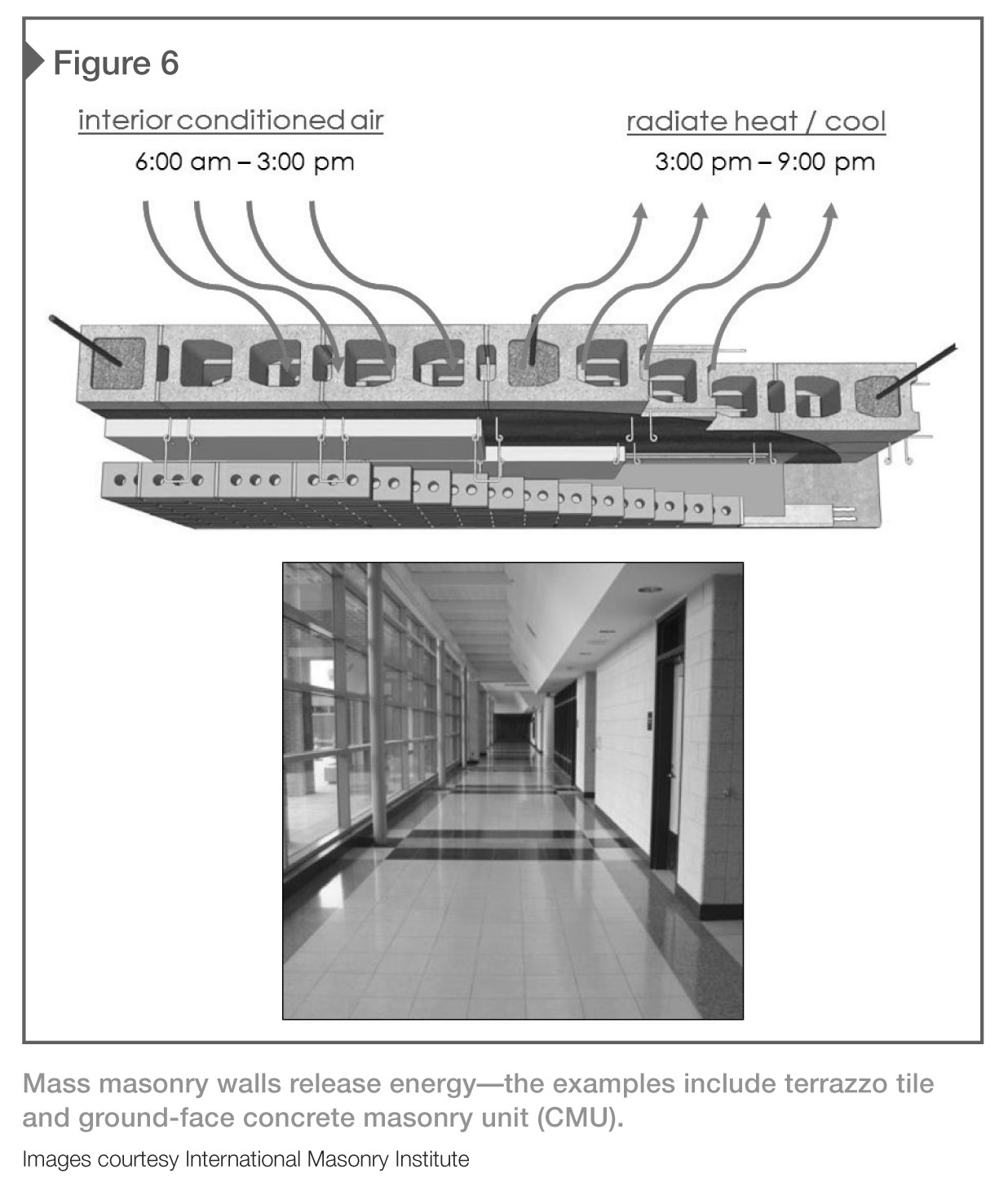
Stud wall assemblies have much higher requirements (i.e. R-7.07) than masonry mass walls because of the benefits of thermal mass, which are now quantified in the national energy codes. Advantages of thermal mass masonry include:
? reduction of temperature swings;
? moderation of indoor temperature;
? storage of heating/cooling for later release (Figure 6);
? reduction and shift of peak heating and cooling loads to non-peak hours; and
? passive solar design.
(Designers should check National Fire Protection Association [NFPA] 285, Standard Fire Test Method for Evaluation of Fire Propagation Characteristics of Exterior Non-load-bearing Wall Assemblies Containing Combustible Components, and manufacturer’s requirements when specifying combustible insulation and/or combustible air-moisture-vapor barriers in wall systems—special detailing and letters of engineering equivalency may be required.)
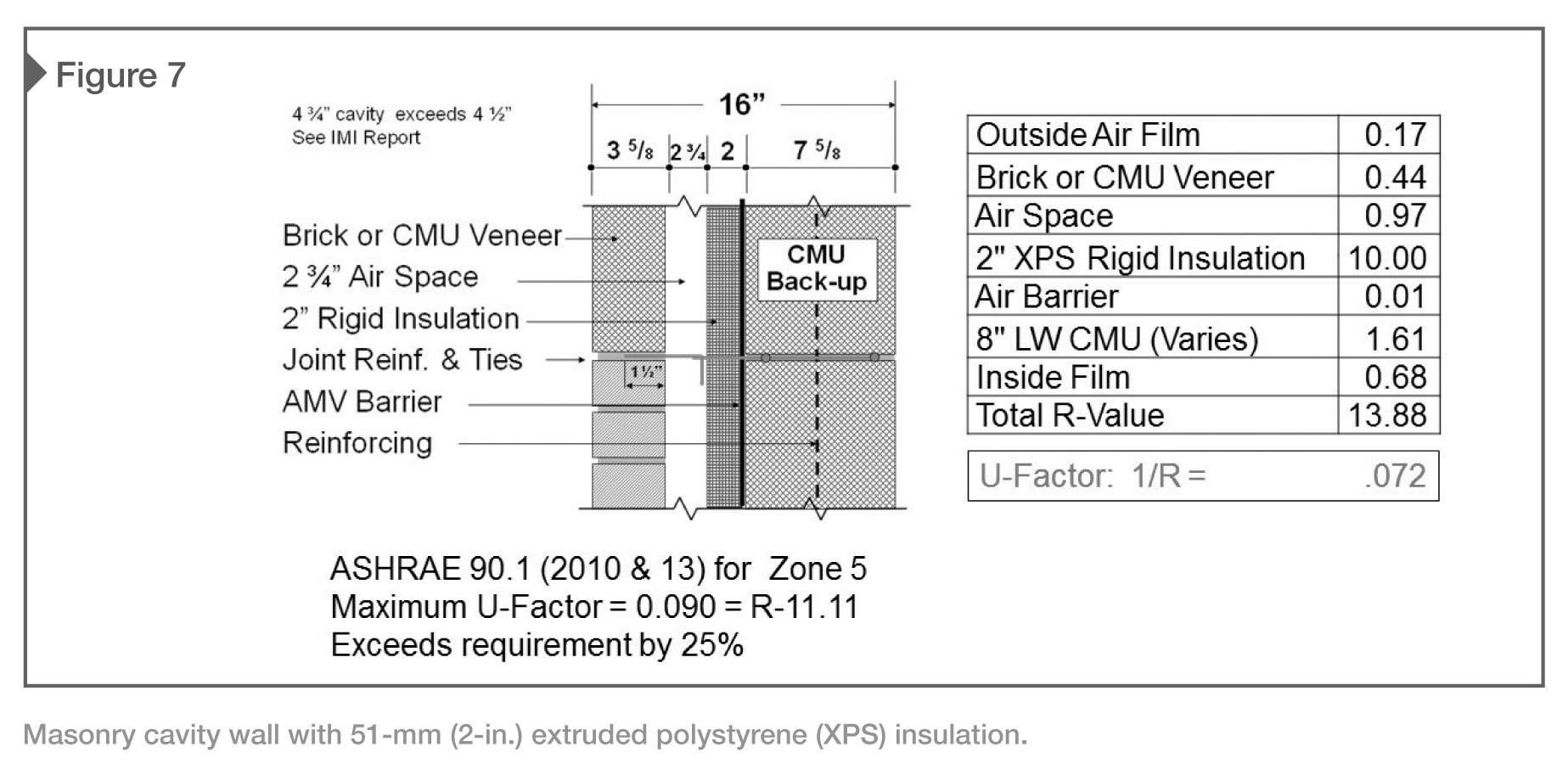
Example 1?masonry cavity wall with 2-in. rigid XPS insulation
A typical 406-mm (16-in.) masonry cavity wall with a 100-mm (4-in.) masonry veneer, 70-mm (2 ¾-in.) air space, 50-mm (2-in.) rigid insulation, an air/moisture/vapor (AMV) barrier, and 200-mm (8-in.) lightweight CMU back-up is shown in Figure 7. Using prescriptive Method B, the ASHRAE table requires an assembly U-factor of U-0.090 or R-11.11 for Zone 5. The resulting R-value of 13.88 exceeds the required minimum of R-11.11 by 25 percent.
If Method A was used, the ASHRAE table requires R-11.4 ci, which, for example, would equal about 64 mm (2 ½ in.) of extruded polystyrene (XPS) insulation or by rounding up to a more common size 76 mm (3 in.). As noted, Method B is not as efficient as Method A. By using only 50-mm (2-in.) XPS (R-10) continuous insulation and the component material R-values, the cumulative assembly (R-13.88) exceeds the required minimum of R-11.11.
Example 2?masonry cavity wall with 3-in. rigid XPS insulation
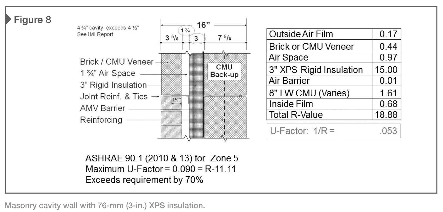
A typical 406-mm (16-in.) masonry cavity wall with a 100-mm (4-in.) masonry veneer, 45-mm (1 ¾-in.) air space, 76-mm (3-in.) XPS rigid insulation, an air/moisture/vapor (AMV) barrier, and 200-mm (8-in.) lightweight CMU backup is shown in Figure 8. The wall assembly complies with both prescriptive Methods A and B, and exceeds the assembly minimum by 70 percent—this means it is suitable for ‘high-performance’ and LEED projects. The overall wall configuration remains at 406 mm, and the resulting air space is 45 mm.
Example 3?masonry veneer with 6-in. stud backup and 2-in. high-R insulation
Masonry veneer with steel-stud backup is more complex than masonry veneer with CMU backup because of higher minimum R-value requirements due to energy loss through steel studs, cavity width limitations, and dewpoint locations. The maximum cavity (distance from face of steel stud to back of brick) is 114 mm (4 ½ in.) in accordance to MSJC’s Building Code Requirements and Specifications for Masonry Structures, Chapter 12.
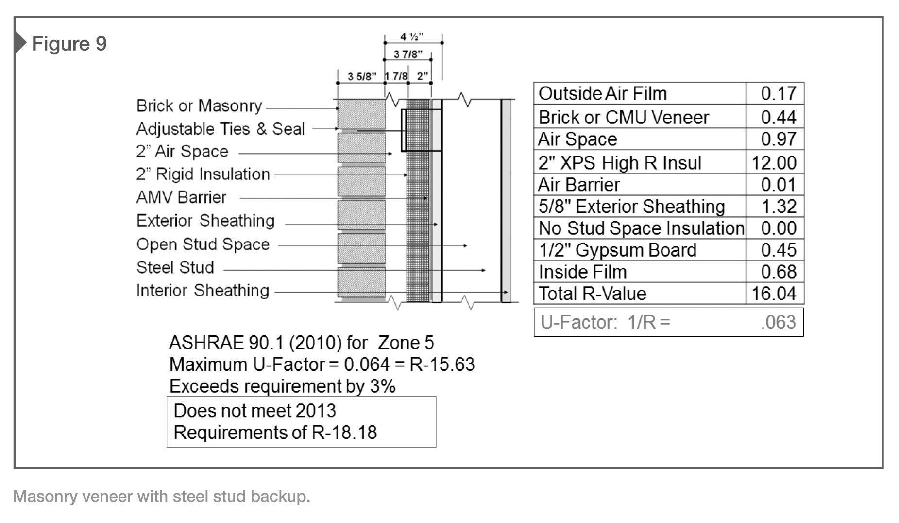
This is prescriptive design only and engineering calculations are common for cavities exceeding 114 mm, which require more insulation to meet energy requirements. Also, many manufacturers now make stronger masonry ties, fasteners, and anchors that can easily span wider cavities. The wall configuration in Figure 9 yields a total R-value of 16.04 (U=0.063) which is only three percent over the 2012 IBC/IECC/ASHRAE 2010 requirements, and does not meet 2015 IBC/IECC/ASHRAE 2013 R-value of R-18.18.
It is important to note this wall configuration uses ‘high-R’ (2 1/8-in.) XPS insulation (R-5.6 per inch), which is more expensive than 50-mm (2-in.) XPS (R-5 per inch). This example does not factor in any additional stud backup energy loss, which will vary with stud spacing and wall configurations.
Example 4?masonry veneer with 6-in. stud backup and 3-in. high-R insulation
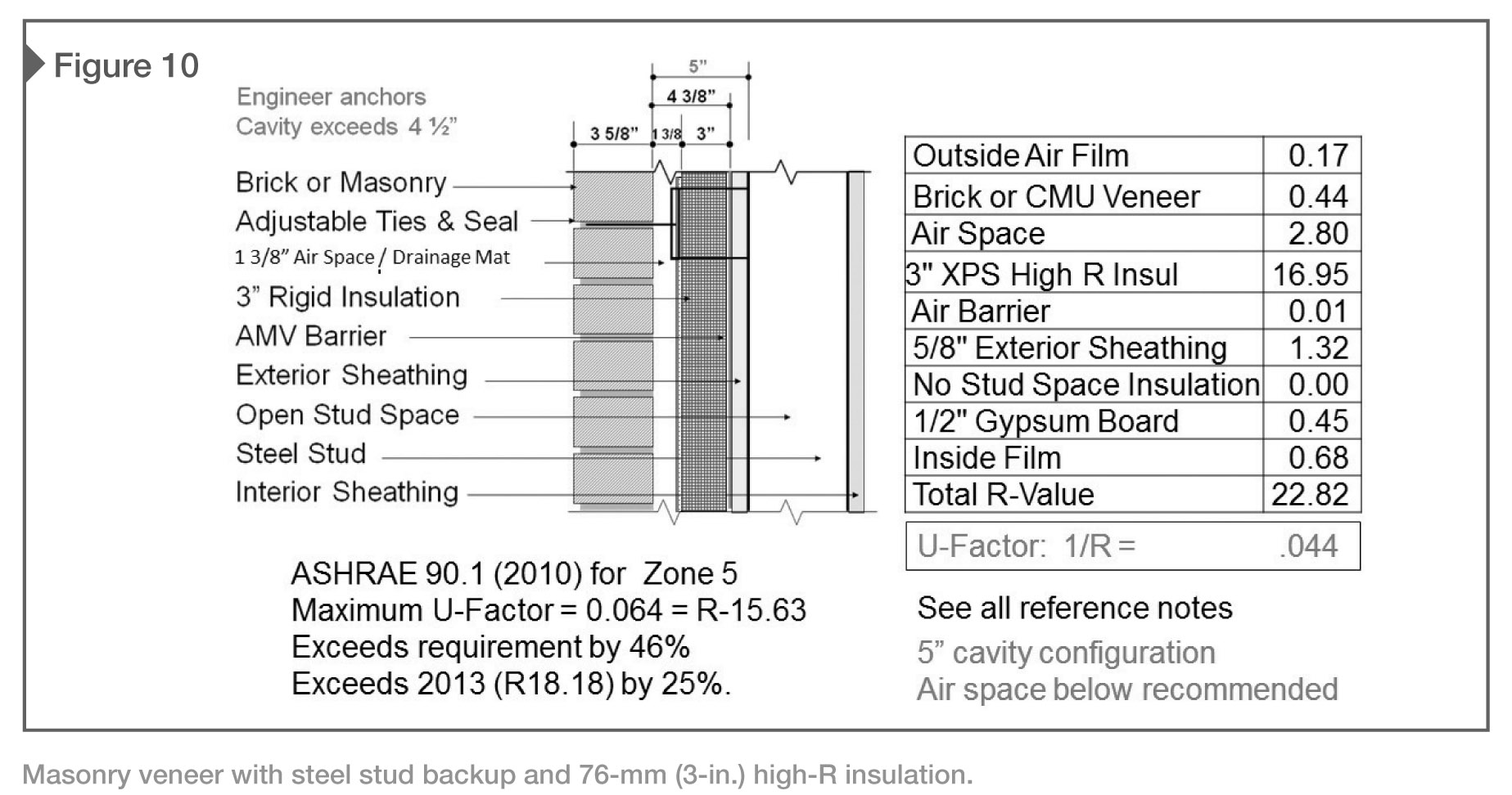
Figure 10 demonstrates use of 76-mm (3-in.) ‘high-R’ XPS insulation. The cavity has been increased to 127 mm (5 in.), which will require engineered anchors. The resulting 35-mm (1 3/8-in.) air space is well below the 50-mm (2-in.) industry standard, and less than the 38-mm (1 ½-in.) acceptable air space.
One option is to add a 9.5-mm (3/8-in.) continuous drainage mat to assist at preventing mortar bridging, which can lead to efflorescence, water penetration, restricted water drainage and reduced air flow. The net air space of 25 mm (1 in.) would also meet MSJC’s code minimum. Another option would be to simply increase the overall cavity to 140 mm (5 ½ in.), which would result in a 48-mm (1 7/8-in.) air space.
The wall configuration in Figure 10 yields a total R-value of 22.82 (U=0.044), which exceeds the 2012 IBC/IECC/ASHRAE 2010 requirement of R-15.63 by 48 percent, and the 2015 IBC/IECC/ASHRAE 2013 R-value of R-18.18 by 25 percent.
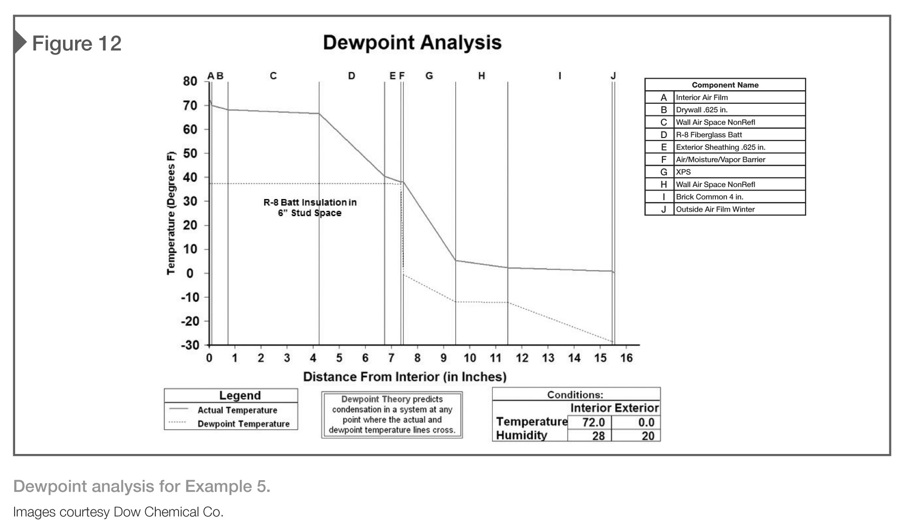
Example 5?masonry veneer with 6-in. stud backup, 2-in. XPS insulation, and R-8 stud space insulation
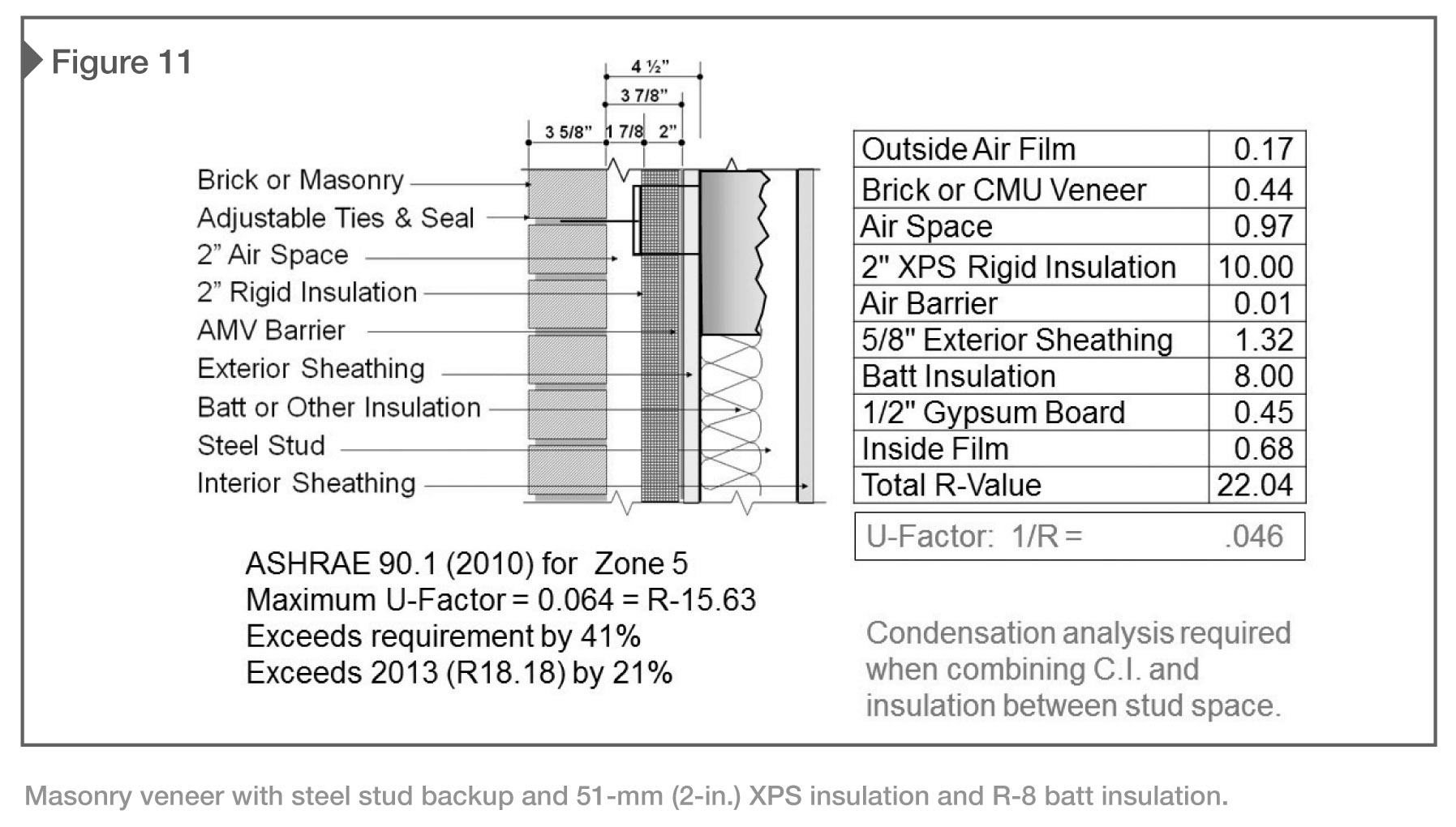
Another option for insulating steel stud backup walls is to combine rigid cavity insulation with insulation between the studs. In this example, the 114-mm (4 ½-in.) maximum cavity is maintained the air space is an acceptable 48 mm (1 7/8 in.). Caution is advised as a dewpoint analysis is required to reduce the potential for condensation within the stud space. Generally, the maximum stud space insulation should not exceed R-8 in Climate Zone 5 conditions. Most designers avoid additional insulation in the stud space.
The wall configuration in Figure 11 yields a total R-value of 22.04 (U=0.046), which exceeds the 2012 IBC/IECC/ASHRAE 2010 requirement of R-15.63 by 41 percent, and the 2015 IBC/IECC/ASHRAE 2013 R-value of R-18.18 by 21 percent.
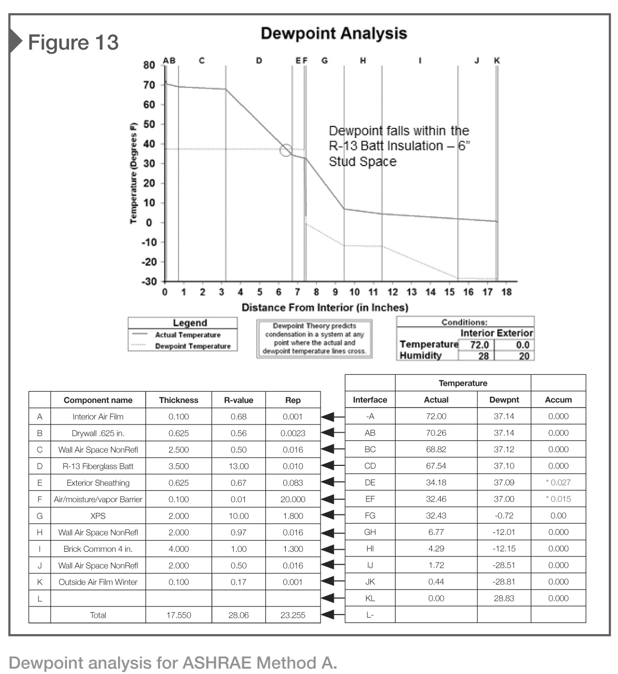
The dewpoint theory predicts condensation in a system at any point where the actual and dewpoint temperature lines cross. Figure 12 represents the dewpoint analysis for the ‘Example 5’ stud wall configuration. For this particular assembly, if the rigid insulation was changed to R-10 and the stud space insulation was R-13 as shown for Method A Table 5.5-6 of ASHRAE 90.1 2013, the dewpoint would fall in the stud wall space (Figure 13). This is not recommended.
It is also important to carefully review air/moisture/vapor barrier properties and location within the various wall systems for the building’s climate zone.
Which bridge to take: Structural or thermal?
Continuous insulation is defined in ANSI/ASHRAE/IES 90.1-2013 (I-P Edition) Section 3.2 (“Insulation”) as:
Insulation that is uncompressed and continuous across all structural members without thermal bridges, other than fasteners and service openings. It is installed on the interior or exterior or is integral to any opaque surface of the building envelope. [emphasis added]
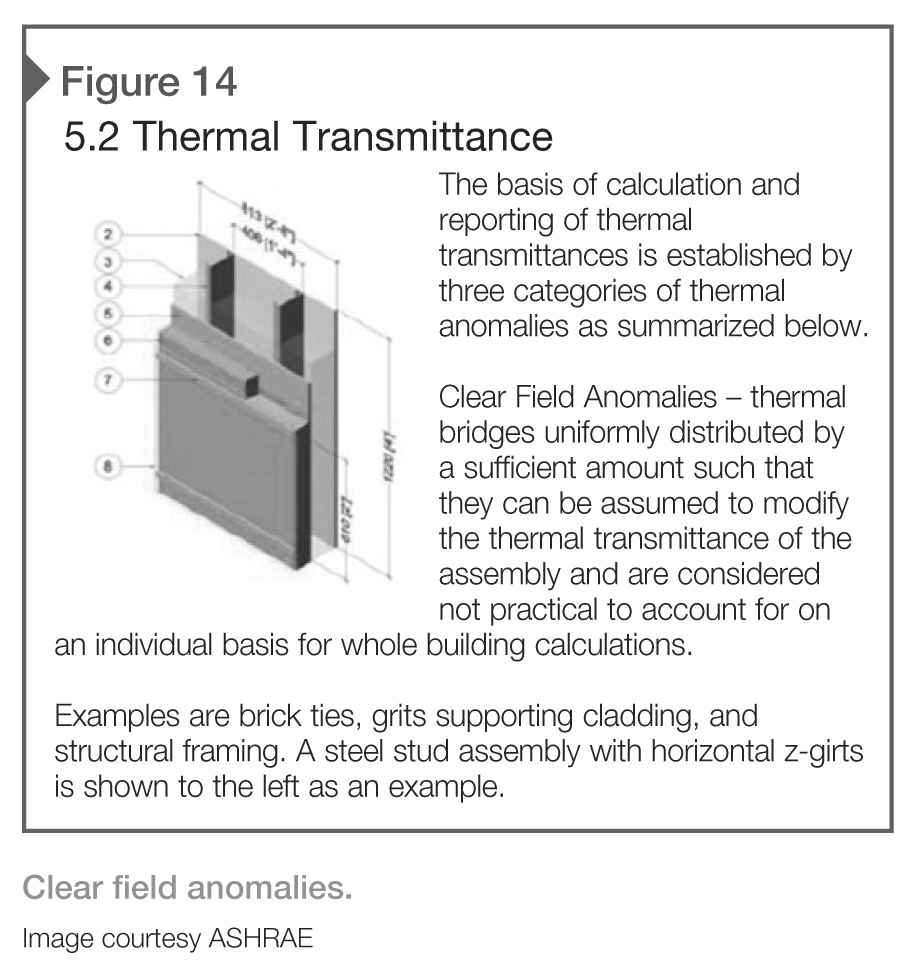
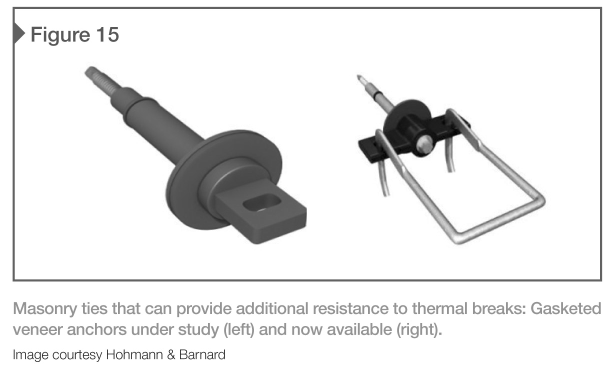
Therefore, the code does not require a reduction in R-value calculation for masonry ties, fasteners, or anchors. This is further confirmed in the ASHRAE report, “Thermal Performance of Building Envelope Details for Mid-and High-rise Buildings” (5085243.01 MH 1365-RP July 6, 2011). Brick ties are considered a clear field anomaly, and are not considered practical to take into account on an individual basis for whole building calculation (Figure 14). However, companies now manufacture various masonry ties that provide additional resistance to thermal breaks (Figure 15).
Today, masonry ties must not only effectively hold the veneer in place (especially with wider cavities), but they must also be as energy-efficient as possible while helping to create an airtight seal at the penetration point of the air barrier. New anchors are being developed with ‘thermal breaks’ built into the anchor itself to further reduce any thermal bridges, with 2D and 3D modeling showing that a properly designed thermally broken anchor can improve energy performance of a wall assembly.
‘Gasketed’ veneer anchors are critical to the success of any air barrier system, as those penetrations can not only allow potential moisture infiltration, but also be a thermal weak point that can break the continuity of the building envelope. Obviously, the study of these new anchors primarily is involved with metal stud construction where thermal bridging issues have been most prominent.
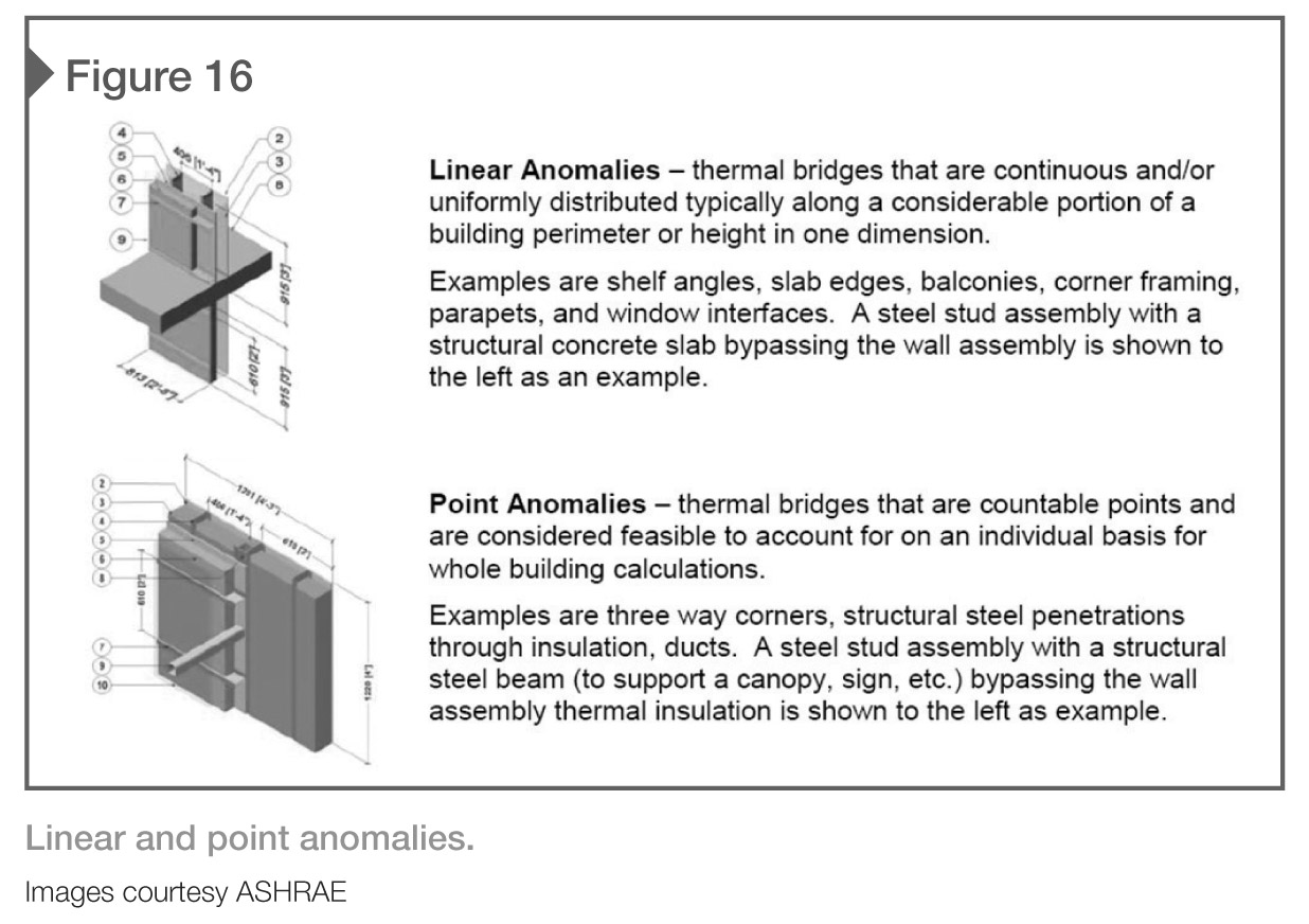
Other construction assemblies and connections require closer consideration and evaluation. Examples of these linear anomalies are shelf angles and slab edges. Typical masonry shelf angles can be suspended away from the structure by clip angles or pre-manufactured supports—this allows the rigid insulation to continue behind the shelf angle, reducing thermal loss. Of course, there are still clip angles at periodic spacing (e.g. 1220 mm [48 in.] on center [oc]) as determined by the structural engineer of record that must be considered. These fall into the classification of point anomalies as shown in Figure 16.
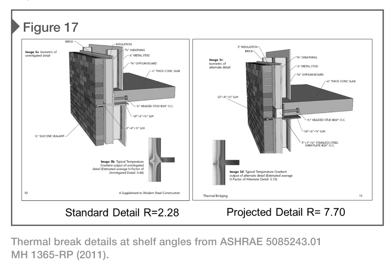
It is essential the architect and engineer determine which bridge to take. The structural bridge would favor the shelf angle tight to the structure to reduce the cantilevered loads and save costs. The thermal bridge would use the clip angles to reduce energy costs. How does one decide? Simply add up the costs and compare (Figure 17).
If the added structural cost to add clip angles to the relieving angles for a project is $100,000 and the owner will save $400 month in energy consumption, it will take 20 years to ‘break even.’ While this is just a hypothetical example, it is important to carefully analyze the cost benefits.
It is also important to analyze the entire building envelope, including the percentage of fenestration. If the building has a significant area of glass with R-values of R-3 to R-5, the cost to increase the R-value for a small percentage of the opaque walls at shelf angle may be unwarranted. Once again, evaluations are required.
Conclusion
There are various masonry wall assemblies to achieve energy-efficient designs that comply with, and exceed, national energy requirements, LEED, and other high-performance standards. It is important to remember that ‘over-insulating’ opaque walls is not always cost-effective. There is a point where thicker insulation with a higher R-value just does not yield a return on investment (ROI). While buildings may consume a great deal of energy, a greater amount is used with electric lights, equipment, HVAC, and plug loads than through the loss of energy with the building envelope.
Traditional masonry walls can be designed using current technology for insulated-ventilated façades that are practical, energy-efficient, and cost-effective. These walls can also be transformed into modern, contemporary buildings.
Notes
1 The term “residential” does not apply to basic single family homes. As its name suggests, ASHRAE 90.1 provides energy standards for buildings “except low-rise residential buildings” based on the following definition: low-rise residential buildings: single family houses, multi-family structures of fewer above grade, manufactured houses (mobile homes), and manufactured houses (modular homes). Energy requirements for these buildings are indicated in the International Residential Code (IRC). (back to top)
Richard Filloramo is area director of market development and technical services for the International Masonry Institute (IMI) New England Region’s Connecticut/Rhode Island Office. He holds a bachelor’s of science in architecture from Ohio State University and an associate’s degree in construction technology from Wentworth Institute of Technology. Filloramo has more than 40 years of experience in the masonry industry, and has been involved with the design, construction, or inspection of more than 5000 projects. He served as the national IMI liaison for building codes and standards and is a member of the Masonry Standards Joint Committee (MSJC)—the code-writing body responsible for the Masonry 530 Code. Filloramo can be reached at rfilloramo@imiweb.org.
Chris Bupp is director of architectural services for Hohmann & Barnard, and has been involved in the construction industry for nearly 30 years with the building envelope as his primary area of expertise. At H&B, he works with architects, structural engineers, and building envelope consultants as an educational resource and as a national speaker and writer on the subject of masonry wall design. Bupp also serves on two committees at the Air Barrier Association of America (ABAA). He can be reached at chrisb@h-b.com.

