

by Chuck Mears, FAIA, Ryan Rademacher, AIA, ?Sheri Carter, AIA, and Michael Chusid, RA, FCSI, CCS
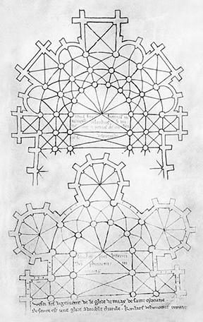
During the medieval period, complex Gothic structures were built from drawings that communicated a designer’s overall vision without detailing specific means of construction. Master craftsmen translated designs into buildable structures using simple tools available at the time. Now, in some respects, the construction industry has come full circle.
Complex concepts envisioned by contemporary designers are being translated into buildable structures by a new generation of master builders. The differences, however, are today’s building materials can be considerably lighter weight than stone masonry of yore, and the craftsman’s tool kit includes building information modeling (BIM) capabilities.
Recent advances in cold-formed steel (CFS) framing illustrate this transition. The American Iron and Steel Institute (AISI) defines cold-formed steel as:
shapes manufactured by press-braking blanks sheared from sheets, cut lengths of coils or plates, or by roll-forming cold-rolled or hot-rolled coils or sheets; both forming operations being performed at ambient room temperature, that is, without manifest addition of heat such as would be required from hot forming.
CFS uses thinner materials with different structural characteristics than hot-rolled sections. Thanks to the efforts of AISI, Cold-formed Steel Engineers Institute (CFSEI), and other industry organizations, there are well-established engineering and fabrication guidelines for orthogonal CFS structures. However, using CFS for complex curved or faceted surfaces still relies on master crafters—now called subject matter experts (SME)—with specialized skills and knowledge.
The relationship between an SME and the project’s architect/engineer (A/E) and contractor has to be defined within terms of the project’s contract documents. For example, a specialist could be a:
- ?vendor assisting the A/E or contractor on a promotional basis;
- ?professional consultant hired by the A/E or contractor to advise on, or take responsibility for, engineering;
- ?properly licensed design professional hired by the contractor; or
- ?supplier providing framing for a project. (Any recommendations to improve or simplify framing would require appropriate change orders or construction change directives prior to deviating from construction documents.)
The BIM boom
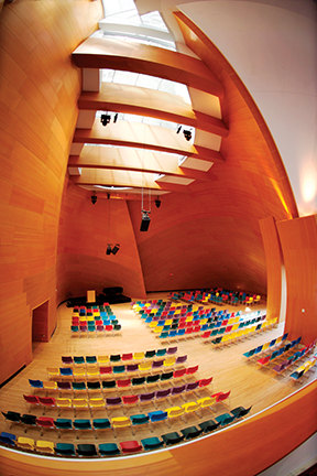
Walt Disney Concert Hall in Los Angeles is a poster child for complex architectural surfaces. Many of the curvilinear finishes inside the Frank Gehry-designed building are shaped and supported by armatures of CFS members. The project’s contractor hired an SME to engineer framing solutions and create BIM files to drive computer numerical controlled (CNC) fabrication, communicate with other trades, coordinate dimensions within tolerances of primary structure, and detect clashes with other building elements.
While BIM may someday be as well-established as hammer and chisel are to stone masonry, the construction industry is still grappling with the best way to use its digital toolkit. Architects that design complex surfaces tend to be with the same firms gravitating toward BIM. Their models assist in visualizing spaces or establishing overall geometry, yet often lack information necessary to construct a project.
Even when BIM is available for a project, the construction contracts are usually based on sets of drawings and models are issued to builders solely for reference. Despite this, many construction contracts stipulate contractors provide digital data that can be added to the BIM file to show framing and facilitate clash detection. Amidst all this data, someone still has to figure out the best way to install framing and make the translation from virtual to physical. As one experienced installer explains it, “the model still doesn’t tell me where I need to put the stud.”
In addition to growing complexity of architectural shapes and digital practices, the steel framing industry has also evolved.
“In just the past five years, the steel stud industry has undergone a fundamental change,” said Steven A. Etkin, executive vice president/CEO of Association of the Wall and Ceiling Industry (AWCI). “Where once the ‘generic’ steel stud reigned as king, it is rapidly being dethroned by the expanding use of proprietary products with unique profiles, varying stud thickness, and even specialized coatings.”
New tools simplify fabrication of complex shapes. For example, curving studs or tracks used to require a time-consuming process of making multiple cuts in members and then securing them into shape with straps, screws, or welds. New tools bend framing members by making origami-like plications (folds or pleats), and computer numerically controlled (CNC) lasers cut intricate shapes from light-gage steel such as tabs or entire CFS shapes that simplify assembly of components.
Further, codes and standards affecting CFS have been recently revised. There are now three industry associations with competing certification standards. Increased attention also has to be given to sustainability. A subject matter expert has to stay abreast of advances like these.
Alternative to other materials
One North is an urban infill office and retail development currently being constructed in Portland, Oregon. Intended to achieve Platinum certification under the Leadership in Energy and Environmental Design (LEED) program, the Holst Architecture design calls for deep apertures—pods—at windows to funnel daylight into offices yet block direct sun that could create glare and contribute to excess heat gain in the building. The building has continuous insulation with high thermal resistance. To minimize thermal bridging through insulation, each aperture will attach only by its four corners to the building.
The project’s structural engineer proposed welded hot-rolled rectangular steel tubes to create a cage at each aperture; trusses would hang from attachment points at sides of apertures and beams would span ?6 to 9 m (20 to 36 ft) between trusses. Hot-rolled steel is frequently used for structures like this because the engineering and detailing are well understood.
The architect, however, was willing to push the envelope and consider alternatives. Working with an SME, they were able to reduce weight of apertures by about 60 percent. LEED v4 uses ‘dematerialization’ to describe reduction in materials required for construction. This has the direct benefit of reducing environmental impact of extracting, fabricating, and transporting building products. It achieves additional benefits by reducing structural loads, thereby reducing material requirements throughout superstructure and foundations. Since raw steel is a significant part of a steel structure’s cost, switching to lightweight CFS helped reduce estimated in-place cost of apertures by about 30 percent.
Had hot-rolled steel been used, cages would have required infill framing to support finishes. In a CFS system, structural members also serve as substrate for finishes, simplifying construction and contributing to the material’s economy.
Simplified framing logic
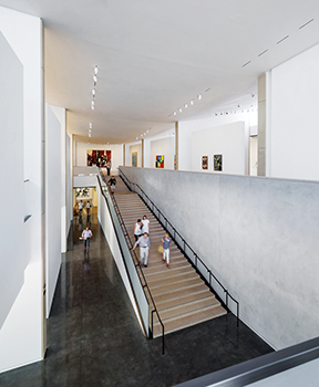
The Anderson Collection of 20th Century Art goes on display this fall in a new building on Stanford University’s campus in Palo Alto, California. The building, designed by Ennead Architects, has an interior capped with an expansive 57 x 24.5 m (187 x 81 ft) ceiling. Referred to as ‘the Belly,’ it is both convex and complex—no two portions of its doubly curved surface have the same shape. Rising from a height of 8.6 m (28 ft) near the building’s center, it reaches 11.7 m (38 ft) around the perimeter where it meets a continuous clerestory that introduces diffused daylight into the hall.
Given the prestige of collection and importance of ceilings to the gallery’s interior design, the project was the antithesis of the ‘beat-to-fit, paint-to-match’ attitude that can lead to forming complex surfaces by brute force. While the architect built a digital model defining ceiling contours, means and methods of construction were not detailed. The contractor initially considered a conventional tee-bar ceiling suspension grid, but decided it would be too difficult to maintain dimensional tolerances working with straight framing elements. The SME was asked for assistance in determining framing logic for the ceiling and to develop a method of installing it to exacting dimensions.
The SME began by building a more precise model of the space for better control of the ceiling’s geometry. Its recommendation to use a system of curved light-gage steel ribs located 1.2 m (4 ft) on center (o.c.), was accepted; the firm was hired to detail and fabricate a system to meet California’s rigorous seismic-resistance criteria and state-approval process.
Cold-formed channels were used to suspend ribs from the roof deck to obtain more stability than would have been practical with wire hangers usually employed for ceiling suspension. The channels penetrated the roof deck and were attached to horizontal member on top of the deck so loads on fasteners were in shear, not tension—this meant greater seismic reliability. Holes in the deck were drilled based on dimensions taken from the SME’s BIM.
Each rib has a unique profile, and the SME established control points on each one to continuously fit the desired shape. Especially close tolerances were required, since deviations in ceiling surface would have been visually exaggerated by glancing light from clerestories. The ribs were factory-curved and color-coded to match installation drawings that, along with sh
op drawings, were generated with information extracted from BIMs. Pre-curved hat channels span between ribs at 400 mm (16 in.) o.c. to provide transverse resistance to seismic forces and more precise control of geometry for finishes.
According to ceiling installer, J&J Acoustics, a conventional ceiling suspension grid would have required scaffolding for a work platform, but the CFS suspension system could be installed from telescoping boom lifts. While scaffolding was eventually required to apply an acoustical plaster finish, use of lifts to install the suspension system gave the general contractor more time with unrestricted access to work floor.

Ruled surfaces or curved framing?
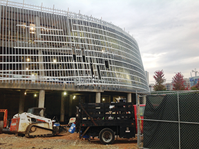
While the Anderson Collection building’s ceiling geometry was complex, it had few interfaces with building elements other than perimeter. The same cannot be said for exterior wall framing of the recently completed National Center for Civil and Human Rights (NCCHR) in Atlanta, designed by The Freelon Group (now part of Perkins+Will) in collaboration with HOK as architect of record. The museum’s exterior walls have compound curvatures, lean inward from bottom to top, and interface with fenestration and curving floor and roof decks.
The A/E designed the walls as ‘ruled’ surfaces—that is, one that can be generated by straight lines. In theory, this should have made it simple to build with linear studs. However, to conform to the complex geometry, studs had to be installed out of plumb, and the degree and direction of inclination varied from stud to stud. Combined with walls’ inward tilt, this meant gravity and wind loads, along with deflection of superstructure, had to be resolved as forces acting both axially and perpendicularly to double-leaning studs. For example, each connection at intermediate floor levels required a unique hot-rolled steel bracket for studs to lean against in addition to normal stand-off clips.
Faced with the complexity, framing contractor Principle Partners retained the SME to model structure, establish X-Y-Z coordinates, and assist with installation.
While the project was executed with the straight framing members the architect envisioned, SME determined installation could have been simplified by using curved CFS framing members instead of straight studs. Curved studs could be installed plumb to resist gravity loads without the customized brackets. Eliminating the brackets and simplifying labor would more than offset the cost of curving the studs.
Window openings would also be simplified because the hot-rolled steel used to frame openings could be replaced by conventional CFS headers. The project had advanced to the point, however, where it was impractical to accept the proposed redesign.
This demonstrates why subject matter experts are best brought onto project teams early in the design process. According to the American Institute of Architects’ (AIA’s) 2007 Integrated Project Delivery: A Guide, this:
allows the designer to benefit from the early contribution of constructors’ expertise during the design phase, such as accurate budget estimates to inform design decisions and the pre-construction resolution of design-related issues resulting in improved project quality and financial performance.
Panelization
The SME was also able to expedite construction by panelizing a multi-faceted suspended ceiling that zigzagged above the NCCHR’s 230-m2 (2500-sf) events space. The installer initially hired the consultant just to prepare shop drawings for the complex framing. However, as the deadline for the museum’s opening drew nearer, the general contractor determined either scaffolding to assemble framing in-place or fabricating the ceiling on the floor would have interfered with other activities to be performed in the building.
The light weight of light-gage framing made it simple to transport and handle panelized elements. Panels as long as 9 m (30 ft) were light enough to be carried into the building as needed, and then quickly lifted into place with two or three scissor lifts (depending on configuration).
Conclusion
The success of each of these projects was a team effort that included an A/E to establish vision, a contractor to execute that vision, and an SME to provide specialized expertise. This type of three-way relationship is relatively new in the light-gage steel industry, but well-established in many other aspects of construction. With precast concrete, for example, the architect or engineer of record will specify loads and performance criteria for structure, but design of actual members is delegated to specialist consultants and fabricators.
As mentioned, the SME could be one of a number of parties, ranging from vendors and consultants to suppliers, as defined in the project documents. However the team is put together, SMEs can be said to fill the role of the guilds that built the Gothic structures referenced at beginning of article—applying the art and science of their trade toward making great architecture.
Chuck Mears, FAIA, is CEO and chief design officer of Radius Track, a firm specializing in engineering and fabrication of curved and complex cold-formed steel (CFS) framing tools and systems. He can be reached at chuck@radiustrack.com.
Ryan Rademacher, AIA, is design director at Radius Track. He uses building information modeling (BIM) and parametric design to integrate digital fabrication with artisanal craft. He can be reached at ryan@radiustrack.com.
Sheri Carter, AIA, is the marketing manager at Radius Track. She has a master’s degree in architecture from the University of Buffalo and was in architectural practice before moving into building product sales and marketing. Carter leads the firm’s efforts in product development, sustainable design, and continuing education. She can be reached at sheri@radiustrack.com.
Michael Chusid, RA, FCSI, CCS, started his career working for a cold-formed steel framing manufacturer in 1978. He has been a marketing and technical consultant to many firms in the industry since then. He can be reached at michael@chusid.com.


It’s really interesting as to what you can do with steel. With that, you can really make whatever you want in addition to making whatever others want. With BIM, is it still practical to use in this day and age?