Sizing pipes: Exploring CPVC as a material alternative
by Tom Attenweiler and Don Townley

Sizing a water distribution system for a commercial space requires consideration of several factors—from pressure to fixture count to pipe material. Calculating all contributing factors is essential to meeting code requirements as well as ensuring proper operation of the system.
This article focuses particularly on chlorinated polyvinyl chloride (CPVC)—a semi-rigid material providing pipes that are versatile, durable, and cost-efficient, making them well-suited for both commercial and industrial applications.
Pipe sizing considerations
The first step in pipe sizing for commercial structures is determining the water pressure entering the building from the city. There is pressure regulation at the water meter, which is where engineers and designers start tabulating friction losses contributing to a system.
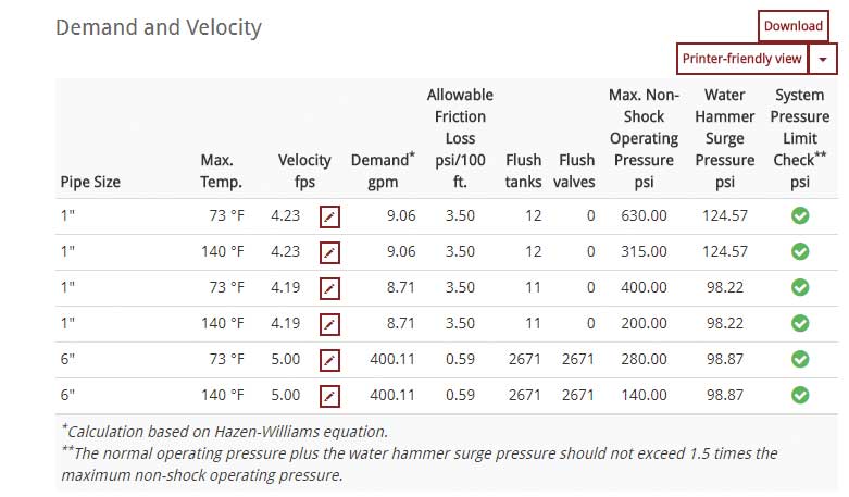
Understanding these losses enables the designer to translate them into an average pressure drop per 30.5 m (100 ft) for the system. This drop is a fundamental parameter required for calculation of the system velocity and, ultimately, the flow rate (or “demand”).
Plumbing codes establish guidance for the number of fixture units serviced by a given flow rate. In addition to its dependence on pressure drop, flow rate also relies on the inner diameter of the pipe. Due to this relationship, the size of the pipe can be adjusted to achieve the necessary flow rate required to service the desired number of fixture units. However, the maximum number of fixture units capable of being serviced depends on the available pressure in the system.
Pressure coming into the system is typically limited by local plumbing codes to 552 kPa (80 psi), although most systems average around 275 to 345 kPa (40 to 50 psi). Other factors, including altitude, may also come into play. Generally, the pressure needs to remain around 103 kPa (15 psi) once it reaches each fixture.
Determining if this pressure will be reached requires adding up the friction losses in the system. This can either be achieved manually or through use of a sizing calculator, whereby a designer inputs incoming pressure and then lists known pressure losses. Every element in the water system, from the meter to a bend, results in pressure losses.
Typical friction losses/gains include:
- water meters;
- pressure-reducing valves;
- submeters; and
- elevation loss/gain.
After tabulating friction losses, a designer can determine the total pressure drop, which is then reported on building plans.
Pipe size selection is outlined in the International Plumbing Code (IPC):1
Water pipe sizing procedures are based on a system of pressure requirements and losses, the sum of which must not exceed the minimum pressure available at the supply source. The pressures are as follows:
- Pressure required at fixture to produce required flow.2
- Static pressure loss or gain (due to head) is computed at 0.433 psi/ft (9.8 kPa/m) of elevation change.
e.g. Assume that the highest fixture supply outlet is 20 ft (6096 mm) above or below the supply source. This produces a static pressure differential of 20 ft by 0.433 psi/ft (2096 mm by 9.8 kPa/m) and an 8.66 psi (59.8 kPa) loss. - Loss through water meter. The friction or pressure loss can be obtained from meter manufacturers.
- Loss through taps in water main.
- Losses through special devices such as filters, softeners, backflow prevention devices, and pressure regulators. These values must be obtained from the manufacturers.
- Loss through valves and fittings. Losses for these items are calculated by converting to equivalent length of piping and adding to the total pipe length.
- Loss due to pipe friction can be calculated when the pipe size, the pipe length, and the flow through the pipe are known. With these three items, the friction loss can be determined. For piping flow charts not included, use manufacturers’ tables and velocity recommendations.
Sign up for our weekly newsletter
Architectural materials and methods delivered right to your inbox
- CSI News & Notes: CSI’s impact earns official recognition; celebrate leaders, mentors, and innovators; and more
- CSI News and Notes: CSI spring certification exams open; scholarships available; and more
- CSI News & Notes: CSI MSR heading to San Diego; spring certification exams open; and more
- To Be Specific: Why CDT Should Be Your First Move
- CSI News & Notes: CSI Fellows share member benefits; and a New Year’s Resolution to keep
Products


Read the Latest Issue