by Anthony J. Katona, CDT

According to the National Roofing Contractors Association (NRCA) and nearly all single-ply roof membrane manufacturers, the term ‘ponded water’ can be defined as “any accumulation of water that remains on the surface of the completed roof system 48 hours after the last rainfall.” ‘Standing water’ refers to any remaining water that will evaporate before 48 hours after the last rainfall.
The intention of this article is mainly to provide insight on the many important elements of proper drainage on low-slope commercial roofs, exclusively those with internal primary and secondary roof drainage systems, and the impact they have on effectively eliminating ponded water conditions.
Images courtesy Alliance Roof Consultants, Inc.
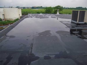
While there are many benefits of having a well-drained low-slope commercial roof system, two significant advantages are that of roof structural safety and the prevention of premature deterioration of the roof system. For these reasons, one thing this author evaluates during a roof audit is how well the roof drains. Or, in other words, has the roof been designed and constructed to alleviate ponded water? Proper drainage cannot be emphasized enough when discussing or reviewing the requirements of any well-drained low-slope commercial roof system (Figure 1).
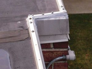
The building in Figure 2 is located in the mid-Atlantic region near a large city on the East Coast. The building was unoccupied at the time of a cursory audit. The main concern was the lack of adequate drainage. In the author’s experience, this condition of ponded water is more prevalent when a roof system is installed over an existing one—this idea is supported by the two discrete edge metal details visible in Figure 2.
Consequences of ponding
It has long been recognized by construction industry professionals, including forensic structural engineers, architects, building envelope and commercial roof consultants, and plumbing engineers specializing in designing a roof system with internal primary and secondary roof drains, the primary cause of failure is excessive water ponding.
According to Roof Drainage, published by the Roof Consultants Institute Foundation (RCIF), “With a density of 28 kg (62.5 lb)/cf³, water is a heavy substance. A 25-mm (1 in.) depth of water adds a weight of 2.3 kg (5.2 lb)/ft² on the roof. The design live load for a typical roof is 9 kg (20 lb)/ft², and the building codes allow for a reduction in this figure so that the structural elements with large tributary areas can be designed for a live load of only 5.4 kg (12 lb/ft²).” (For more information, read the Roof Consultants Institute Foundation’s [RCIF’s] Publication No. 20.03, Roof Drainage.)
For economic reasons, this live load reduction is often invoked in the structural design of a roof deck assembly, particularly long span roofs. Unfortunately, this limit can be exceeded by the weight of only 6 mm (2.5 in.) of ponded water—a poorly drained roof can accumulate this much water fairly quickly during heavy downpours with disastrous results such as:
- roofing bitumens have certain compounds that dissolve under the sustained pressure of standing water, thereby reducing the membrane’s life; and
- some adhesives used in single-ply membranes deteriorate under similar conditions.
Although many of the new adhesives manufactured and used today are scientifically more advanced and the room for workmanship-related errors is lessened, there are more concerns about temperature (i.e. too cold or hot) and high humidity levels during the various stages of application.
There is no debate that a well-designed, well-constructed, and well-drained roof system outperforms a roof exhibiting poor drainage. Since proper drainage is important, most of the commercial roof manufacturers will not issue a no-dollar limit (NDL) warranty on projects without removing all existing roofing material, and installing a completely new system from the roof deck up. Alternatively, a disclaimer may be added stating the exclusion of coverage in areas where ponding occurs.
In the example of a re-roofing project, a cover board is typically placed between the existing roof and the newly installed system. However, moisture trapped between the roof membranes either in the form of liquid, solid, or gas causes certain types of roof insulations (e.g. fiberglass, wood-fibered, and/or perlite) to deteriorate and compress, resulting in the creation of low spots throughout the field of the roof.
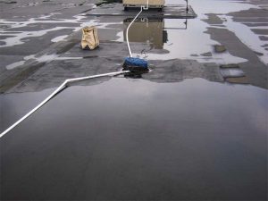
In Figure 3, a single roof drain was observed to be at an elevation higher than the adjacent roof area, thereby preventing proper drainage. This situation could be exacerbated by the lack of an adequate amount of strategically positioned and/or properly sized internal roof drains, in addition to zero slope of the roof in these areas.
A lack of well-defined waterways are also interrupted by rooftop units (RTUs) and thus limiting the options available to properly address ponding (Figure 4). For instance, structural steel support beams are likely installed directly under the area where the mechanical
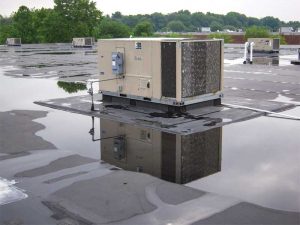
equipment is mounted to the roof. In the author’s experience, this would almost always include the presence of other structural and/or mechanical elements on the interior of the building. This could limit the ability to install additional roof drains, complete with primary and secondary drainage components and a tapered rigid insulation drainage cricket system, at the roof deck’s low point where ponded water is most prevalent.
In this case, the feasibility of properly connecting additional primary and secondary roof drains in a specific building depends on several factors such as:
- location and height of building;
- actual ceiling height;
- existence of a suitable network of drain conductors and vertical and horizontal drainpipe lines; and
- applicable building and plumbing codes.
Roofs with minimal slopes present additional challenges. For example, it is likely there is only 3 to 6 mm (1/8 to ¼ in.) per foot slope or zero slope in many areas of the roof in Figure 3. The height of the base curb of the RTU would be substantially compromised by the installation of tapered rigid insulation crickets. One of the solutions would be to temporarily remove all RTUs’ roofing material and design a temporary fix with new drains and crickets to try to reduce the amount of ponded water. However, this measure would not be recommended by the author because water trapped between two discrete roof systems can leak when one cuts through to the top of the roof deck.
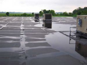
As observed in Figure 5, the installation of additional new internal primary roof drains would not eliminate ponding, as the underdeck steel infrastructure and related mechanical equipment would require the construction of drainage crickets. These crickets must be large enough to create adequate slope from one side of the low point to the other side to offset the existing slope of the roof so as to direct the water runoff into the primary roof drains instead of simply displacing it higher up the slope.
However, this plan would be contingent on attaining the appropriate building permits and complying with the locally adopted building and plumbing codes. Depending on the project’s location, its use, and the codes adopted by the authorities having jurisdiction (AHJ), the addition of new internal roof drains could fall short of the intended purpose because some plumbing codes now require the installation of an independent secondary roof drainage system.


