

by Alfredo Bustamante, PE
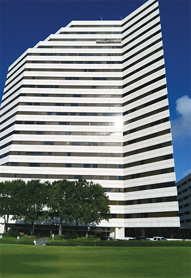
Built in 1982, Capital One Plaza is a 22-story structure in Houston, Texas. The building exterior wall consists of ribbon windows and 30-mm (1 1?8-in.) thick travertine panels connected to precast concrete spandrel panels.
The cladding was fabricated by placing travertine panels face-down in formwork, installing stainless steel wire loop anchors into predrilled holes in their back surface, and casting concrete against this to encapsulate the stainless steel anchors.
A plastic bond-breaker membrane was applied to the back of the travertine panel before casting the concrete to prevent bonding of the concrete to the panel. Each precast concrete panel is clad with six travertine panels and the joints between the travertine panels were filled with a flexible sealant material.
The travertine panels are oriented on the building with bedding planes spanning horizontally, which is typically done for weather resistance. The travertine panels’ height is approximately 1.2 m (4 ft), with the length varying between approximately 1.5 and 2.1 m (5 to 7 ft). The exposed columns at the east entrance to the building are clad with curved travertine stone units.
The east exterior entrance of the building consists of approximately 465 m2 (5000 sf) of travertine pavers set in a mortar setting bed. The plaza paver system includes the following components, from the top down:
- 910-mm (36-in.) square, 20-mm (3?4-in.) thick travertine pavers;
- 25.4-mm (1-in.) thick unreinforced mortar setting bed;
- drainage mat;
- waterproof membrane; and
- structural concrete slab (above occupied basement) and concrete slab-on-grade.
The 30-year-old travertine exterior wall panels and plaza pavers at Capital One Plaza exhibited distresses such as cracking and spalling. Such distress in thin travertine stone panels presents several challenges in developing a reliable repair approach, and at the same time minimizing the possible negative aesthetic impact from the repairs on the building’s exterior wall.
A comprehensive evaluation was performed on the exterior wall and pavers at the building, and consisted of field observations, laboratory testing, structural calculations, and mockup repairs to understand the condition of the travertine exterior wall panels, design repairs, select replacement stone, and establish stone repair criteria required to maintain the building’s original appearance.
An acrylic-modified mortar mix—consisting of white portland cement, hydrated lime, sand, and a proprietary liquid admixture—was designed and implemented to parge the exterior of the building to limit dirt accumulation within the voids in the stone and provide the building owner the desired monolithic appearance to the travertine panels. Innovative panel connections and repairs were designed and constructed to provide supplemental support to the travertine panels.
More specifically, the renovation work consisted of:
- removal and replacement of approximately 250 travertine exterior wall panels;
- removal and replacement of nearly 90 travertine pavers;
- repair in-place (with counter-sunk and helical anchors) about 1000 cracked travertine panels;
- restoration cleaning of approximately 7000 exterior wall travertine panels;
- application of parging over entire travertine surface; and
- removal and replacement of sealant at joints between travertine units.
Project challenges
The project team encountered various design and construction challenges in the Capital One Plaza project.
Access
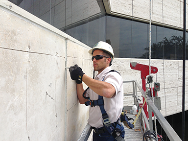
Up-close observation of the travertine cladding units was required to assess their condition and properly develop repair documents. The evaluation phase—as well as the repairs—needed to be performed with swingstage access. This required proper certification in compliance with Occupational Safety and Health Administration (OSHA) regulations of the façade access equipment, which was performed via in-situ load testing of the façade access support system’s permanent components.
Identifying cause
The up-close observations revealed cracks within the travertine panels varying in width between 0.12 and 0.64 mm (0.005 and 0.025 in.), and the cracks were found with different conditions, including faulted cracks, epoxied cracks (apparently repaired during original construction), and stone veins that have opened over time. During the project’s evaluation phase, three travertine panels—two with visible cracks—were removed for observations.
The cracks in the two travertine panels were a reflection of the shrinkage cracks in the precast concrete backup wall system. This is called reflective cracking, and it occurred because the bond-breaker membrane between the travertine panels and the precast concrete panels was not properly applied or was missing, allowing the concrete to bond to the stone.
Analysis of as-built conditions and lab testing
The design of travertine veneer systems requires careful consideration of many factors, including:
- design loads (lateral and gravity);
- physical and mechanical properties of the stone;
- natural variability of the stone;
- age-related strength loss;
- factors of safety prescribed by industry organizations;
- stone strength at connections;
- connection method; and
- panel defection under loads?.
To properly evaluate travertine cladding panels, removal of at least one panel is often required to evaluate the support conditions and the strength of the stone. During the evaluation phase at Capital One Plaza, five travertine panels were removed from the building’s exterior in order to make samples required for laboratory testing in accordance with ASTM International C880, Standard Test Method for Flexural Strength of Dimension Stone. This test was performed to evaluate the current flexural strength of the travertine panels in both orientations relative to bedding. Test results compared minimum strength requirements listed in ASTM C1527, Standard Specification for Travertine Dimension Stone, which provides minimum physical properties for travertine with a history of successful use for general building and structural purposes. The test results showed the travertine panels removed for testing meet the minimum 3.4-Mpa (500-psi) flexural strength requirements as tested in accordance with ASTM C880.
Using the flexural strength test data of panels removed from the building, calculations were performed to evaluate the as-built travertine cladding spans. Wind load analysis was performed according to 2006 International Building Code (IBC), the applicable building code at the time of the evaluation. The current industry standard for the flexural factor of safety for travertine is ‘8.’
The calculations showed the vast majority of the existing travertine panels were adequate without the need of supplemental anchors to reduce spans. Where supplemental anchors were required, flexural strength test data allowed the spacing of supplemental anchors to maximize panel spans. Flexural strength testing provided the designers with a refined approximation of the current travertine strength, which led to significant cost savings to the building owner, compared to the repair of all panels.
Repairs
Based on the investigation, different types of repairs were considered in developing drawings and specifications. The 7th edition of the Dimension Stone Design Manual was also referenced while designing, developing, and detailing the repairs. These repairs consisted of removing and replacing approximately 250 exterior wall panels and 90 pavers along with in-place repairs of about 1000 additional exterior wall panels.
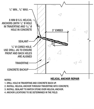
Figures 1 & 2
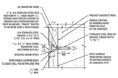
Custom-made counter-sunk anchors (Figure 1) were designed to provide lateral and gravity support for the new panels. Laboratory testing was performed on these anchors in accordance with ASTM C1354, Standard Test Method for Strength of Individual Stone Anchorages in Dimension Stone, to confirm the counter-sunk anchor’s adequacy for this application. The placement of these anchors was optimized based on structural analysis calculations using maximum panel spans (using flexural strength test results) and tested anchor strength. A range of placement horizontally and vertically within the panel was included in the drawings for construction tolerances, allowing the contractor some freedom of anchor placement. This was required to avoid putting an anchor at possible natural travertine deficiencies. For the same reason, a similar placement range was designed and specified for the helical anchors.
Helical anchors (Figure 2) provided lateral support for the new panels and supplemental lateral support for the existing panels repaired in-place by connecting the panels to the concrete backup. Helical anchors are self-threading into stone during installation, and the anchor strength is derived from this mechanical interlock of the anchors with the stone. The primary contributing factor to the strength of helical anchors is the depth of engagement.
Since the travertine panels at this project were only 30 mm (1 1?8 in.) thick, the strength of supplemental helical anchors was maximized by increasing the depth of engagement. This was accomplished by installing anchors at a 15-degree angle from a horizontal plane perpendicular to the face of the travertine panel, minimizing the counter-sink of the anchors, and specifying anchors with a reduced taper at the head (where the anchor does not engage the panel).
The new paver system consisted of a mortar bed with thin-set exterior stone paving. The joint between the pavers were filled with compressible backing rod and a multi-component polyurethane slope-grade sealant. The slope-grade (as opposed to self-leveling) sealant was specified because it requires tooling the joint, which can improve adhesion to the paver substrate. During the project’s construction phase, a strict quality assurance (QA) approach was adopted so the engineer could determine the location of required repairs for each panel in the field, as well as observe the final installation of most repairs performed. The QA process consisted of visual inspections (by the engineer of record for the repairs) of each exterior travertine panel and paver on the building prior repairs, in order to determine the specific repair required for each travertine panel and paver. A follow-up inspection of approximately 20 percent of the completed repairs was also performed.
Additionally, there was a detailed tracking of the repair quantities to accurately process the contractor’s applications for payment. This field presence also enabled the forecasting of the possible need for additional stone panels. It allowed the contractor to order stone panels with sufficient lead-time to meet the project schedule and not be delayed by the stone quarry in Italy.
Aesthetic and performance requirements
Part of the scope of repairs also included panel replacement. This presented a difficult task to both design professionals and contractors because the selection of stone panels needed to closely match the color, texture, and veining characteristics of existing weathered travertine. To address this issue, stone selection criteria was developed, comprising guidelines for testing, submittals, samples, preparation for transportation, and mockups. It included:
- Ship initial samples of 305 x 305 mm (12 x 12 in.) to the owner for preliminary aesthetic approval, and provide results of independent laboratory tests certifying the stone is from the same blocks of the quarry identified for this project, and meets its design requirements.
- The stone used for repairs shall be taken from the same area of the quarry and will also maintain a consistent color, surface finish, and veining pattern.
- The stone shall be cut with the same grain direction as the existing stone on the building.
- All travertine panels shall be cut accurately to shape and dimensions in order to maintain the following setting tolerances in descending order of preference: alignment of vertical joints; and alignment of stone wall panels with windows to maintain existing joint dimensions and in/out alignment.
- The surface finish shall match the existing stone surface finish. No readily visible quarry saw marks are acceptable.
- Both front- and back-faces of the stone panels are to be parged. The back parging is to be performed at the quarry to provide some additional strength to the stone and minimize the possibility of breakage during shipment.
- Initial testing—ASTM C880, Standard Test Method for Flexural Strength of Dimension Stone—of samples from the actual stone to be supplied for use on the building are to be performed by an independent testing laboratory before placing the travertine panels order.
The selection criteria also included photographs of stone deficiency examples so the supplier and contractor had a visual aid to allow them to better select travertine panels.
All counter-sunk anchors were covered with travertine plugs adhered with a specialty two-component ultraviolet (UV)-stable patching compound that closely matched the adjacent stone surface. Masking of the stone surface around the patches was specified to minimize the possibility of this material’s unwanted application to the stone surface, which could present an aesthetic concern. To facilitate the masking operation, the contractor installed the tape prior to the anchors, and cored or drilled through tape and stone. The travertine plug was specified to provide a better aesthetic match than sealant, and to avoid hydrophobic spots on the travertine panels where sealant is present and the possible sealant fluid migration into the stone, which could present significant aesthetic concerns after rainfall.
Since travertine inherently has many voids, accumulated dirt creates an undesirable appearance. In this project, the building owner wanted to eliminate the ‘dirty’ look of the panels and pavers. A cleaning and parging protocol was developed to remove the accumulated dirt and prohibit dirt from accumulating again, while providing a cleaner and more monolithic appearance to the travertine panels (Figure 3) and pavers (Figure 4). This was accomplished through employing a specialty parging mix with a proprietary bonding agent and without artificial color additives that could discolor over time.
Figure 3
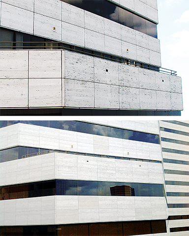
Figure 4
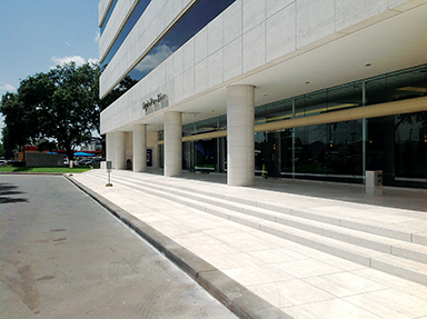
A chemical cleaning protocol was used on the exterior wall before parging application, while pavers were pressure washed solely with water. A mockup of the paver parging was performed at the initiation of the project for the building owner to evaluate aesthetic performance of the pavers for two months before the parging work started. The project was completed on schedule in the second quarter of 2014. The building owner has since received positive feedback regarding the clean appearance of the building façade and paver system.
Conclusion
It is the author’s hope design professional and building owners acknowledge the importance of evaluating distressed travertine (and other stone) cladding based on a comprehensive approach including material evaluation and proper assessment of original design and construction issues to understand the cause of the problems and design repairs appropriately.
Mockups of a minimum of two or three full panels for parging and one panel for replacement to evaluate installation and aesthetic performance of travertine cladding repairs are paramount to the success of this type of project. A comprehensive approach, performed in combination with an effective maintenance and periodic condition survey program, could considerably extend the service life of existing travertine cladding.
The maintenance and periodic condition survey program consists of up-close observations by a qualified design professional every two to five years (starting with the first survey two years after repairs are completed), followed by necessary repairs of distress identified. The frequency of periodic surveys should be adjusted depending on the findings from the first and subsequent surveys. Periodic exterior restoration cleaning may also be required as part of the maintenance plan to maintain the clean appearance of the travertine panels.
| Capital One Plaza Project Team |
| Project name: Capital One Plaza Travertine Cladding and Paver Renovation Client: CBRE Designer: Wiss, Janney, Elstner Associates, Inc. (WJE) – MIA Member Stone supplier/fabricator: Mariotti, Carlo & Figli S.p.A. Stone installer/General contractor: Western Waterproofing Sizes: Pavers are 914 x 914 mm (36 x 36 in.) x 19.05 mm (3?4 in.) thick Cladding panels–varied: 1.2 x 1.5 to 2.1 m (4 x 5 to 7 ft) x 30 mm ?(1.18 in.) thick Finish: Sawn belt finish (and back parged) from the quarry and parged on-site Quantity of new panels/pavers: 250 for exterior wall, 90 pavers Quantity of exterior wall panels repaired in-place (approx.): 1000 Quantity of exterior wall panels and pavers parged (approx.): 7000 |
Author
Alfredo Bustamante, PE, is a restoration consultant with the Houston office of Walker Restoration. He has been involved with dimension stone cladding and paver repairs, investigation and repairs of parking structures, building foundation evaluation and repairs, non-destructive testing of concrete and masonry structures, and design of repairs for steel structures. Bustamante is a member of the Precast Concrete Institute (PCI) American Concrete Institute (ACI), the American Institute of Steel Construction (AISC), and the International Concrete Repair Institute (ICRI). He can be contacted via e-mail at abustamante33@gmail.com.


Facelift has a lot of advantages, the most important one that ladies will love is that it makes us beautiful even with age.
In 1998, a change in the New Zealand standard for Timber Treatment (as referenced in Acceptable Solution B2/AS1) allowed the use of untreated kiln-dried timber in wall framing. If this untreated timber framing gets wet, the timber starts to rot.
Travertine being what it is this was bound to happen. It is a thin and frail product in comparison to concrete. Glad it was able to be repaired though.