

Horizontal holes
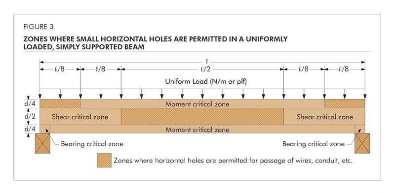
Like notches, holes in glulam remove wood fiber, thus reducing the net area of the beam at the hole location and introducing stress concentrations. These effects cause a reduction in the capacity of the beam in the area of the penetration. Hence, horizontal holes in glulam timbers are limited in size and location to maintain structural integrity. Figure 3 shows the zones of a uniformly loaded, simply supported beam where the field drilling of holes may be considered. These non-critical zones are located in portions of the beam stressed to less than 50 percent of design bending stress and less than 50 percent of design shear stress. For beams of more complex loading or other than simple spans, similar diagrams may be developed.
The APA – The Engineered Wood Association Technical Note, Effect of Large Diameter Horizontal Holes on the Bending and Shear Properties of Structural Glued Laminated Timber, Form V700, provides additional engineering guidelines where larger horizontal holes than those specified here cannot be avoided.
Field-drilled horizontal holes should be used for access only and not as attachment points for brackets or other loadbearing hardware unless specifically designed as such by the engineer or designer. Examples of access holes include those used for the passage of wires, electrical conduit, small-diameter sprinkler pipes, fiber-optic cables, and other small, lightweight materials. These field-drilled horizontal holes should meet the following guidelines.
Hole size
The hole diameter should not exceed 38 mm (1.5 in.) or one-tenth of the beam depth, whichever is smaller, with the exception of 25 mm (1 in.) diameter or smaller holes as noted in the section below.
Hole location
The hole should have a minimum clear distance, as measured from the edge of the hole to the nearest edge of the beam, of four hole diameters to the top or bottom face of the beam and eight hole diameters from the end of the beam. Note the horizontal hole should not be drilled in the moment-critical zone, as defined in Figure 3, unless approved by an engineer or architect qualified in engineered timber design.
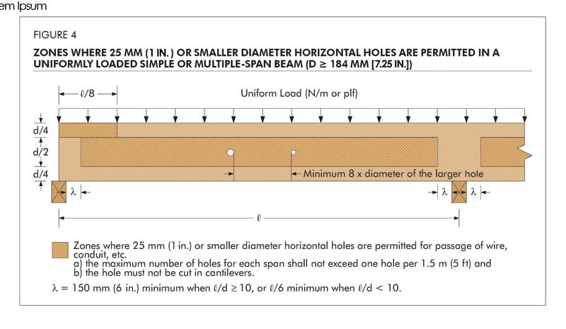
A 25-mm diameter or smaller hole may be cut at the middle half of the beam depth anywhere along the span, except for the area within 152 mm (6 in.) of clear distance between the face of the support and the nearest edge of the hole, provided the following conditions are all met:
• the beam is at least 184 mm
(7.25 in.) in depth;
• the beam is subject to uniform loads only;
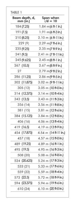
• the span-to-depth ratio (l/d) is at least 10;
• the hole spacing and maximum number of holes must meet the requirements specified in sections “Hole space” and “Number of holes” below; and
• the hole must not be cut in cantilevers (Figure 4).
If the span-to-depth ratio of the beam is less than 10, the 25-mm or smaller hole may be cut in accordance with the provisions listed above, except the location of the hole must maintain a clear distance between the face of the support and the nearest edge of the hole of at least one-sixth of the span.
Hole spacing
The minimum clear spacing between adjacent holes, as measured between the nearest edge of the holes, should be eight hole diameters based on the largest diameter of any adjacent hole in the beam.
Number of holes
The maximum number of holes should not exceed one hole per 1.5 m (5 ft) of beam length. In other words, the maximum number of holes should not exceed four for a 6-m (20-ft) long beam. The hole spacing limitation, as given above, should be satisfied separately.
For oversized glulam members, the guidelines given above may be relaxed based on an engineering analysis.
Regardless of the location, holes drilled horizontally through a member should be positioned and sized with the understanding the beam will deflect over time under in-service loading conditions. This deflection could cause distress to supported equipment or piping unless properly considered (Figure 5).
Vertical holes
Whenever possible, avoid drilling vertical holes through glulam beams. As a rule of thumb, vertical holes drilled through the depth of a glulam beam can reduce the capacity at that location directly proportional to the ratio of 1.5 times the diameter of the hole to the width of the beam. For example, a 25-mm hole drilled in a 152-mm wide beam would reduce the capacity of the beam at that section by approximately 25 percent ([25 x 1.5]/152).
For this reason, when it is necessary to drill vertical holes through a glulam member, the holes should be positioned in areas of the member that are stressed to less than 50 percent of design in bending. In a simply supported, uniformly loaded beam, this area would be located from the end of the beam inward approximately one-eighth of the beam span. In all cases, the minimum clear edge distance, as measured from either side of the member to the nearest edge of the vertical hole, should be 2.5 times the hole diameter. Use a drill guide to minimize ‘wandering’ of the bit as it passes through knots or material of varying density and to ensure a true alignment of the hole through the depth of the beam.
Holes for support of suspended equipment
Heavy equipment or piping suspended from glulam beams should be attached so the load is applied to the top of members to avoid tension perpendicular-to-grain stresses. Any horizontal holes required for support of significant weight, such as suspended heating and cooling units or main water lines, must be located above the neutral axis of the member and in a zone stressed to less than 50 percent of the design flexural stress (Figure 3, page 14). Fasteners supporting light loads, such as light fixtures, must be placed at least four laminations or 25 percent of beam depth, whichever is greater, away from the tension face of the member. The design capacity of the beam should be checked for all such loads to ensure proper performance.


What is your opinion of using 1/4 or 3/8 steel as a flitch plate bolted to 2x lumber in stead of lvl spans?