Achieving ADA compliance for door hardware
by brittney_cutler | September 1, 2021 12:00 am
 [1]
[1]by Kevin Tish, CDT, AOC, CFDAI, DHC, DHT
The Americans with Disabilities Act (ADA) is a law in the United States designed to make public spaces more accessible to people with disabilities. It requires buildings and other places used by the public to be accessible for people with physical, sensory, or mental impairments. This means areas like parking lots, bathrooms, doorways, and water fountains must adhere to certain standards to be ADA-compliant.
The standards discussed in this article are based on the national standards; however, local codes may have variances. It is important to check with local building code officials for the requirements in effect in different jurisdictions.
There are several key considerations for door hardware to comply with ADA requirements such as the approach to the door, the opening clearance, thresholds, surfaces, operating hardware, closing speed, opening force, and exit door signage.
 [2]
[2]The History of ADA
The ADA was signed into law by U.S. President George H.W. Bush in 1990. It was created to ensure people with disabilities can access public accommodations, state and local government services (including schools), transportation, and telecommunications.
Between 1990 and 1999, the act was governed by the ADA. There were no standards or explanatory materials to clarify the ADA law, but this changed when accessibility was addressed by the International Code Council (ICC), beginning with the International Building Code (IBC) published in 2000 under Chapter 11, Accessibility.
Today, there are two national standards for accessibility used to ensure compliance with ADA: The Americans with Disability Act Accessibility Guidelines (ADAAG);[3] and ICC A117.1, Standard for Accessibility and Usable Buildings and Facilities. This article will focus on ADAAG, under which physical disabilities affecting openings include:
• inability to walk or difficulty walking;
• blindness and visual impairments;
• deafness and hearing impairments;
• reaching and manipulating disabilities; and
• difficulty interpreting and/or reacting to sensory information.
 [4]
[4]Accessible Door Design and Hardware: An Overview
Door hardware is one of the many components inside a building that must meet ADA standards. The main priority for building compliance is to provide measures that will enable individuals with disabilities, including employees, to physically enter a facility, and to provide access to areas where goods and services are available to the public. This includes lobbies and restrooms. For building owners, this includes removing barriers, such as plants, desks, and walls that could easily hinder accessibility.
Section 404 concentrates on doors, doorways, and gates that are part of an accessible route. There are two door designs: swinging and sliding. Each has its own specifications for width, height, length, and hardware selected (i.e. knobs versus levers), open space on the sides of doors to accommodate wheelchairs, or other mobility devices, etc.
 [5]
[5]Approaches
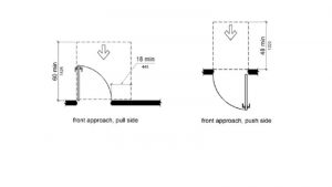
To understand the approach requirements in accordance with ADAAG 404.2.4.1, Swinging Doors and Gates, consideration must be given to the minimum maneuverability clearance, which is based on how a person approaches—from the pull or push side.
For swinging doors, the front approach to the pull side of a door shall have maneuvering space extending from the front hinge of the door to 445 mm (18 in.) beyond the latch side of the door. The push side of the door shall have maneuvering space at the hinge side extending 305 mm (12 in.) beyond the latch side (see Figure 1).
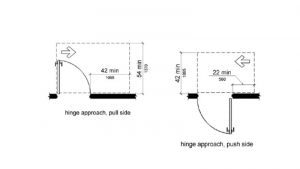
For swinging doors where the approach is from the hinge side, the measurement from the hinge side approach to the pull side shall have a minimum maneuvering space extending 915 mm (36 in.) beyond the latch side (see Figure 2).
 [6]
[6]If the approach is 915 mm from the hinge side, the measurement between the wall and the opposite wall must have a minimum of 1525 mm (60 in.) If the approach is 1065 mm (42 in.) or greater from the hinge side, the measurement between the wall and the opposite wall must have a minimum of 1370 mm (54 in.).
The push side (right side of Figure 2) approach must have 1370 mm measured from the leading edge of the door extending toward the approach side and have 1065 mm from the wall to the opposite wall, without a closing device. If a closing device and latch are used this measurement must increase to 1220 mm (48 in.).
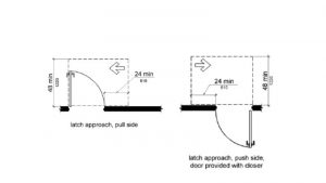
With respect to swinging doors with latch side approaches, the latch to the push or pull side needs a maneuvering space that extends 610 mm (24 in.) from the latch side (see Figure 3). The difference is in the corridor width required. The pull side would require 1220 mm without closer and 1370 mm with closing device. The push side would require 1065 mm without closing device and 1220 mm with a closing device.
Revolving doors and turnstiles are addressed in 404.2.1, which notes revolving doors, revolving gates, and turnstiles shall not be part of the accessible route. This means a separate accessible gate or door must be provided adjacent to the turnstile or revolving door.
 [7]
[7]In this case, two additional doors were installed on either side of the revolving door to meet accessibility requirements.
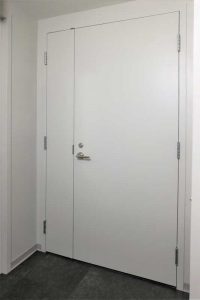
Double-leaf doorways are addressed in 404.2.2, which notes if doorways have two independently operating door leaves, at least one leaf shall meet the specifications on 404.2.3 (clear width) and 404.2.4 (thresholds) (see Figure 4, page 14). That leaf shall be an active leaf. In the case of Figure 5, there is an unequal pair of double doors. The right side-leaf meets ADAAG requirements while the left-side is exempt.
Door Opening Clearance
Door opening clearance is also a key consideration in meeting ADAAG standards. According to 404.2.3, those doorways shall have a minimum clear opening width of 815 mm (32 in.) with the door open 90 degrees, measured between the face of the door and the opposite stop (see Figure 6).
The clearance at the open edge of a doorway shall allow passage without hitting either a fixed object or an obstruction. The clearance at the open edge of a doorway should be no less than 865 mm (34 in.) and not greater than 2030 mm (80 in.) (see Figure 7).
This measurement often gets miscalculated because it is often assumed if an 815 mm door is installed, the specification has been met. This is not the case, however, because the measurement needs to be from the inside—from the hinges to the latch.
This is also a common error in designing sliding doors as the 815 mm requirement applies to these doors also, but the surface mounted hardware will not allow the door to completely slide into the wall (pocket door) or past the wall (barn door/bypassing door).
The U.S. Access Board recommends 38 mm (1.5 in.) clearances around the door pull, which (when added to the size of the pull) reduces the clear opening width by a significant amount (i.e. 38 mm clearance plus 25.5 mm [1 in.] pull diameter plus 38 mm clearance equals 102 mm [4 in.]). This would mean a 915 mm sliding door may meet the 815 mm clearance, but all products would have zero tolerance for installation. Often, these doors are made larger to eliminate sight lines causing additional issues for meeting the clear opening width. It is best practice that sliding doors be made 1065 mm wide to avoid these issues.
The door opening must be at least 815 mm. From the door to the stop is an important measurement because someone in a wheelchair needs to be able to pass through.
Doors in a Series
When there are two or more doors in a series, the minimum space between two hinged or pivoted doors must be 1220 mm plus the width of any swinging door into the space. This concept is illustrated in Figure 8:
• (A) the doors swing in the same direction;
• (B) the two doors swing away from each other; or
• (C) the two doors swing toward each other.
In any case, the measurement of 1220 mm is required. It begins with the wall’s edge or leading edge of the door and is measured to the opposite wall’s edge or leading edge of the door. This is another important measurement to ensure accessibility requirements are met.
Additionally, the door size must be considered and added in with the minimum requirement of 1220 mm for the total required dimensions. In Figure 8, Diagram A, the doors are 915 mm; the corridor with two doors swinging in the same direction must be 2.1 m (7 ft) (915 mm for the door, plus a minimum of 1220 mm between doors equals 2135 mm [84 in.]).
In accordance with ADAAG 404.2.6, Doors in Series and Gates in Series, if the doors swing in the opposite direction, as in Figure 8, Diagram B, the measurement is the minimum 1220 mm. For Diagram C, because the doors swing into the same space, the dimensions of both doors must be considered and added to the minimum requirement for maneuverability of 914 mm for Door A, plus 1220 mm for the corridor plus 914 mm for Door B, equaling 3 m (10 ft).
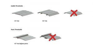
Door Thresholds
To meet accessibility needs, door thresholds can only be a maximum 13 mm (0.5 in.) rise. This measurement is calculated from the finished floor to the highest point on the threshold.
Two common examples of thresholds are saddle and panic. The panic threshold has an additional weatherstrip at the bottom of the door to help seal it. When using panic type thresholds, it is important to remember the total rise (highest point of threshold) is only 13 mm (see Figure 9). Most door undercuts are 16 mm (0.625 in.). Therefore, if one is using panic thresholds at exterior doors, the special undercuts must be addressed, or the door will not seal properly against the gasket.
The use of 13 mm high threshold requires a special undercut of the door. Typical doors have undercuts of 16 mm or 20 mm (0.75 in.); doors with 13 mm high thresholds require a 10 mm (0.375 in.) undercut when using a panic type threshold. To meet ADA requirements a threshold, rise no greater than 13 mm should be specified.
 [10]
[10]Door Surfaces
Door surfaces are often an overlooked element. According to 404.2.10, Door and Gate Surfaces: “Swinging door and gate surfaces within 255 mm (10 in.) of the finish floor or ground measured vertically shall have a smooth surface on the push side extending the full width of the door or gate. Parts creating horizontal or vertical joints in these surfaces shall be within 1.6 mm (0.06 in.) of the same plane as the other. Cavities created by added kick plates shall be capped.”
This standard is often harder to meet in a retrofit project than new construction because narrow-style doors in older buildings often had a 51 mm (2 in.) bottom rail on the door. To create the 255 mm bottom rail for today’s requirements, a kick plate can be added.
This plate protects the door as it gets bumped into while being navigated by a motorized cart or wheelchair as the individual passes through the opening. A common error when using a kickplate to correct the deficiency is not capping it to eliminate the gap from the kickplate to the glass or panel. This may not be the most aesthetically pleasing solution, but it would be considered compliant.
Operating Hardware
Door hardware also has requirements for accessibility. One of the most common disabilities is “reaching and manipulation;” arthritis is the leading cause of disability in the United States, with more than 50 million adults and 300,000 children suffering from some form of the condition.[11]
Door and Gate Hardware
Section 404.2.7 states operating devices installed onto doors (handles, pulls, latches, and locks) must be easy to grasp with one hand and not require tight gripping or twisting of the wrist to operate. Additionally, the highest point of the operating portion of the hardware shall be mounted no higher than 1220 mm above the finished floor. There can be no projection off the face of the door below 865 mm above the finished floor.
 [12]
[12]Opening Force
Section 404.2.9 calls for both interior hinged doors and sliding/folding doors to have an opening force of no more than 22.2 N (2.26 kg [5 lb]). Fire doors are a different matter. They shall have the minimum opening force allowed by the appropriate administrative authority. This does not apply to the necessary force to fully open the door, or the initial energy needed to start the door in motion. It also does not apply to the retraction of latches or disengaging devices used to keep the door in the closed position.
Exterior doors and fire-rated doors are both exempt from door opening and closing forces. Exterior doors must remain closed for security reasons, and the amount of pressure will vary depending on the indoor and outdoor temperatures, outside elements like wind, and the building’s HVAC system.
Fire-rated openings must be equipped with self-closing or automatic-closing devices to keep the door shut. However, to work effectively, doors must remain closed and latched upon activation of the fire alarm as life safety receives higher priority than accessibility.
Closing Speed
Much emphasis is placed on opening force, but the closing speed of a door is equally important. If a door closes too fast, it may hit someone and cause injury. This is addressed in Section 404.2.8, Closing Speed. If a door has a closer, then the sweep period of the closer shall be adjusted so that, from opening position of 70 degrees, the door will take a minimum of three seconds to move a point 76 mm (3 in.) from the latch, measured to the leading edge of the door.
Some closers have a special feature that delays the closing of a door, often called delayed action. This happens when the door is opened to 90 degrees and slowly pivots to 70 degrees. This feature is often used where it is beneficial to have a longer closing time. The closing cycle resumes a normal pace from 70 degrees back to 76 mm from the latch.
It is important to note the delayed action is optional, not required. Only the closing cycle is part of the ADAAG standard. According to 404.2.8.1, “Door closers and gate closers shall be adjusted so that from an open position of 90 degrees, the time required to move the door to a position of 12 degrees from the latch is five seconds minimum.”
This allows individuals more time to freely move through the opening.
Exit Door Signage
ADAAG section 216.4.1 states, “Doors at exit passageways, exit discharge, and exit stairways shall be identified by tactile signs complying with 703.1, 703.2, and 703.5.”
This means, where there is a lit exit sign above an opening, there must also be a tactile sign in Braille on the door or adjacent to the opening 1220 mm centerline of the sign above the finished floor.
National and Local Differences
It is additionally important to check state and local codes for specific standards that have been adopted. For example, the State of California requires—where push plates are furnished—two actuating switches must be used per approach (either in one tall plate or two separate plates), and the centerlines of these switches be located between 178 and 203 mm (7 and 8 in.) and 762 to 1118 mm (30 to 44 in.) above the finished floor.
 [13]
[13]This allows the user to operate it with their hands, feet, or possibly even their cane. In all other states, the mounting height for actuators is between 865 and 1220 mm from the floor or ground.
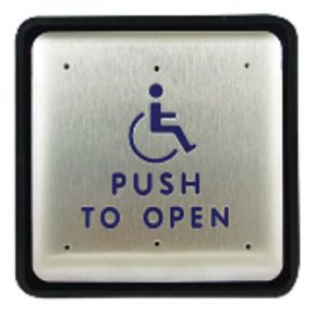
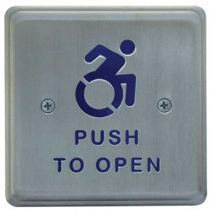
The Accessibility Icon Project[14] is dedicated to changing the symbol for wheelchair accessibility. Specifically, the project claims the current symbol depicts disabled individuals as inactive. Their suggested symbol is an image showing individuals with disabilities more physically engaged; it is beginning to be accepted as the new standard (see Figure 10). In July 2014, New York[15] became the first state to replace the universal handicap icon with the more active, engaging symbol. In 2017, Connecticut[16] followed suit.
If a specifier knows what is expected of a building, it will be easier to make sure everything meets the necessary requirements before construction starts and create a safer, more accessible space for everyone.
Author
 Kevin Tish CDT, AOC, CFDAI, DHC, DHT, is the manager of architectural specification writers at Hager Companies, a leading manufacturer of door hardware. He has 17 years of experience in the door, frame, and hardware industry. Tish volunteers as an instructor for the Door and Hardware Institute (DHI) and is currently serving as the DHI Certification Council Chair. He can be reached via email at ktish@hagerco.com[17].
For more information about designing and construction with ADA standards in mind, see Tish’s CSI Learning Library presentation: ADA-A117.1 – Meeting Accessibility for Doors and Hardware[18].
- [Image]: https://www.constructionspecifier.com/wp-content/uploads/2021/09/The_Sheridan_ALF-F.jpg
- [Image]: https://www.constructionspecifier.com/wp-content/uploads/2021/09/Figure-1_ADA_Front_Approach_Pull_Push_404.jpg
- The Americans with Disability Act Accessibility Guidelines (ADAAG);: http://www.access-board.gov/ada
- [Image]: https://www.constructionspecifier.com/wp-content/uploads/2021/09/Figure-2_Hinge_Side_Approach-ADA.jpg
- [Image]: https://www.constructionspecifier.com/wp-content/uploads/2021/09/Figure-3_Latch_side_approach_ADA.jpg
- [Image]: https://www.constructionspecifier.com/wp-content/uploads/2021/09/Figure-4_chase-park-plaza.jpg
- [Image]: https://www.constructionspecifier.com/wp-content/uploads/2021/09/Figure-5_Hager-22-Water-St-hinges.jpg
- [Image]: https://www.constructionspecifier.com/wp-content/uploads/2021/09/Figure-6_ADAAG_Clear_Width_Doorways_Figure-404.2.3.jpg
- [Image]: https://www.constructionspecifier.com/wp-content/uploads/2021/09/figure-7_clear_width-of-doorways.jpg
- [Image]: https://www.constructionspecifier.com/wp-content/uploads/2021/09/Figure-9.jpg
- condition.: http://www.arthritis.org/health-wellness/about-arthritis/understanding-arthritis/what-is-arthritis.
- [Image]: https://www.constructionspecifier.com/wp-content/uploads/2021/09/Figure-10_Inactive_Motion_ADA_Symbol.jpg
- [Image]: https://www.constructionspecifier.com/wp-content/uploads/2021/09/Figure-11_Forward_motion_ADA_Symbol.jpg
- Accessibility Icon Project: https://accessibleicon.org/.
- New York: http://www.washingtonpost.com/blogs/govbeat/wp/2014/07/29/the-handicap-symbol-gets-an-update-at-least-in-new-york-state/.
- Connecticut: http://www.newmobility.com/2017/01/connecticut-updates-access-symbol/.
- ktish@hagerco.com: mailto:ktish@hagerco.com
- ADA-A117.1 – Meeting Accessibility for Doors and Hardware: https://www.pathlms.com/csi/courses/23937/sections/26089/video_presentations/173357
Source URL: https://www.constructionspecifier.com/achieving-ada-compliance-for-door-hardware/