Achieving compliance with ANSI/ESD S20.20
An effort is underway to revise the definitions of conductive and dissipative within the EOS/ESD Association (it maintains ANSI/ESD S20.20) to eliminate this distinction and the one megaohm threshold that has become the assumed, standard definition.
“This is a problem that predates the current 2014 version of the standard,” said David Swenson, president of the Affinity Static Control Consulting and a director of the EOS/ESD Association. “In the 2014 revision, the committee clarified the requirements for the flooring and footwear system be less than 109 ohms with no lower limit.
“However, the current standards maintain the distinction between dissipative and conductive, which is not relevant in this application, and that may be contributing to confusion among specifiers. This distinction will likely be eliminated in the next revisions of the applicable standards—anything under 109 will be considered conductive—to further address this issue. The most important characteristic is the resistance-to-ground of the person standing on the floor and their walking voltage.”
Moving away from one megaohm
Problems occur with the current standard when one megaohm is set as an absolute threshold and resistance above that level is considered unacceptable or specifiers conclude that if 106 ohms is good, 105 ohms must be even better.
In the first case, it is important to recognize 106 is actually at the high end of the effective range of conductivity, and since resistance is logarithmic it can be difficult to hit a precise target. Additionally, temperature and humidity variations across the floor, along with uneven dispersion of some conductive materials used in ESD control flooring, create variations in resistance measurements.
If resistance of 106 ohms is set as an absolute threshold, it is likely actual overall floor resistance will be closer to 105 ohms—typically lower than necessary.
Even worse, some design professionals have operated on the assumption that if 106 ohms is good, 105 ohms must be even better. This is not the case. Establishing a threshold of 105 ohms does not enhance protection of equipment and increases the likelihood the floor will accumulate charge, which can present risks to workers.
This is why the National Fire Protection Association (NFPA), prior to the development of ANSI/ESD S20.20, developed NFPA 99, Health Care Facilities Code, to prevent injury to workers in ESD flooring applications. Although today’s version of NFPA 99 no longer includes conductive testing methodology or the testing limits, the original version is still referenced today, and says an ESD floor cannot be more than 25,000 ohms when tested at 500 volts.
Newer apparatuses test at 100 volts rather than 500 volts, so that translates into a ceiling of 100,000 (105) ohms. Considering again the logarithmic nature of resistivity that makes it difficult to hit a precise target, establishing a threshold of 105 ohms increases the likelihood the floor contributes to a shock hazard. Lower resistance floors have increased the risk of shock by power sources.
Rather than seeking to achieve the highest possible conductivity level, specifiers and building owners should be looking to reduce conductivity levels to the point where they can safely and consistently meet the ANSI/ESD S20.20 requirement of not discharging 100 volts. That level is usually below one megaohm. This comes back to the ratio between the epoxy coating and conductive additive. Higher volumes of additive will increase conductivity.
Smarter specifications, better materials
Striving for unnecessarily low resistance levels complicates installation and the ability to achieve the architect’s vision. At resistance levels between 106 and 105 ohms, the loading rate, or percent of the flooring material comprising the additives, can be as high as 20 percent.
The higher the loading rate, the greater the risk of hot spots, which make all those involved look bad and require the replacement of the floor. Additionally, control over color and finish is compromised. Not only can manufacturers provide architects and specifiers with greater control over color when coatings do not have high percentages of inherently dark additives that are required to achieve unnecessarily low resistance, but also installers can more easily achieve the desired smooth finish and avoid what is commonly referred to as the “orange peel” effect.
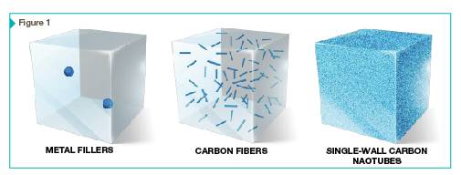
Part of the solution is specifying in the 106 to 109 ohm range. The other part is new flooring additives that create effective conductive networks at lower loading rates. Single-wall carbon nanotubes, for example, can achieve compliance with ANSI/ESD S20.20 at loading rates of 0.1 percent (Figure 1). Due to their unique properties, floors using these materials are not subject to hot spots and provide architects and specifiers with greater control over floor color and finish.
As more flooring manufacturers and installers replace existing additives with newer ones and specifiers better understand the conductivity levels required to safely comply with ANSI/ESD S20.20 resistance-to-ground values, the industry will be better positioned to meet the growing demand for ESD control flooring.
![]() Brandon Atwood is the technical sales director for OCSiAl. He spent over 20 years in the advanced materials industry, and the last four with OCSiAl. He is a graduate of the University of Cincinnati.
Brandon Atwood is the technical sales director for OCSiAl. He spent over 20 years in the advanced materials industry, and the last four with OCSiAl. He is a graduate of the University of Cincinnati.
Sign up for our weekly newsletter
Architectural materials and methods delivered right to your inbox
- CSI News and Notes: CSI Foundation’s construction camp; CSI spring exam; and more
- CSI News and Notes: CSI’s credentials; CSI conference theme; and more
- To be specific – CSI supports young AECO professionals
- CSI News and Notes: CSI’s foundation scholarships, national conference, and Crosswalk
- CSI News and Notes: AI’s impact; CSI 2024 conference, and more


Read the Latest Issue