Achieving compliance with ANSI/ESD S20.20
by sadia_badhon | September 17, 2020 12:23 pm
by Brandon Atwood
 [1]
[1]The global anti-static floor market was valued at $3.1 billion in 2018 and is expected to reach $4.09 billion by 2025, according to Crystal Markets Research. It is not just the electronics manufacturing market spurring this growth. As electronics continue to infiltrate the workplace, the applications for electrostatic discharge (ESD) control flooring are expanding. For example, the automated guided vehicles and robots being deployed in e-commerce warehouses can generate large amounts of static electricity when used on standard flooring. ESD control flooring is required to support these technologies.
In large spaces, such as warehouses, data centers, and manufacturing plants, epoxy-based coatings are dominant. Epoxy-based coatings use a conductive material, such as carbon black, tin oxide, or carbon nanotubes mixed with the epoxy coating to create a conductive network across the floor, which is grounded through copper strips.
Epoxy-based coatings represent the most practical and cost-effective flooring option for larger, concrete floors. Installation is straightforward as the coating is rolled on in a multistep process in which the base layer and topcoat are applied over the primed floor. The major challenge with epoxy is that floor aesthetics and performance are difficult to accurately determine until after the floor is installed and fully cured. Post-installation testing is required to ensure the floor has achieved the specified level of dissipation.
Another challenge with epoxy-based coating, particularly prevalent with some commonly used conductive additives, is the floor may turn out to be darker than desired because of the high volume of the required additive. Hot spots may also appear on the floor.
Hot spots occur when the conductive materials within the coating aggregate in certain areas of the floor, thus creating gaps in the network that prevent the floor from dissipating charge to ground. While they can be caused by poor mixing or installation practices, even flooring systems installed by expert, professional installers can experience hot spots and may leave the building owner with an unusable floor while the installer and manufacturer attempt to determine solutions.
This is where understanding relevant standards becomes essential to design professionals. Determining the right level of conductivity for an ESD control floor can have an impact both on its ability to effectively dissipate static charge and on floor aesthetics.
Understanding the ANSI/ESD flooring standard
ESD flooring specifiers deal with a variety of standards and regulations, but for most applications the American National Standards Institute (ANSI)/ESD S20.20, Protection Of Electrical And Electronic Parts, Assemblies And Equipment (Excluding Electrically Initiated Explosive Devices), is the guiding specification, and with good reason. ANSI/ESD S20.20 is maintained by the EOS/ESD Association, which comprises ESD control professionals with extensive experience in the industry and a deep understanding of the nuances of effectively protecting against equipment-damaging static buildup.
The stated purpose of the standard is to outline “the requirements necessary to design, establish, implement, and maintain an ESD control program for…electrical or electronic parts, assemblies, and equipment susceptible to damage by electrostatic discharges greater than or equal to 100 volts human body model (HBM).”
While it is always a good idea for specifiers to understand the entire standard, there are several pertinent points that need to be highlighted.
First, ANSI/ESD S20.20 specifies a program, and not just a flooring specification. The floor is a critical component of meeting the specification, but it must be considered as part of a broader program, including footwear and training.
Next, the ultimate measure of success is not a certain resistance threshold across the floor but to prevent the accumulation of charge leading to a discharge of 100 volts or more from a person. If the flooring can pass a walking voltage test in which discharge at all points is less than 100 volts, the floor is in compliance with ANSI/ESD S20.20.
Finally, ANSI/ESD S20.20 has continued to evolve based on new knowledge and technological changes. The last major revision of the standard was in 2014, and it clarified some important points about resistance levels in ESD flooring. However, as is often the case, practical application of the standard lagged—revisions and resistance levels, as defined in previous versions, continued to be applied.
The right level of conductivity
Generally speaking, flooring that has resistance to ground of 10^6 to 10^9 ohms is considered dissipative rather than conductive, while flooring with resistance less than 10^6 ohms is considered conductive. This distinction was reinforced by previous versions of ANSI/ESD S20.20 and that led to use of one megaohm (1 x 10⁶) as a convenient threshold for specifiers of ESD control flooring.
Many specifiers continue to use this threshold today despite the 2014 revisions to the standard. Instead of specifying 10^6 ohms as a hard target, the goal when specifying ESD flooring is to be on the low end of the static dissipative range while avoiding the static conductive range. Flooring in the 107 to 109 ohm range, when properly installed and supported by other programs, has been shown to meet the charge accumulation requirements of ANSI/ESD S20.20 while avoiding the risks of too much conductivity. The level of conductivity of the floor is largely determined by the amount of conductive additive used in the coating. To get higher conductivity, one would need to use more additive, and that raised the impact of additive on aesthetics and the risk of hot spots. It also increases the likelihood the floor will become too conductive.
 [2]
[2]An effort is underway to revise the definitions of conductive and dissipative within the EOS/ESD Association (it maintains ANSI/ESD S20.20) to eliminate this distinction and the one megaohm threshold that has become the assumed, standard definition.
“This is a problem that predates the current 2014 version of the standard,” said David Swenson, president of the Affinity Static Control Consulting and a director of the EOS/ESD Association. “In the 2014 revision, the committee clarified the requirements for the flooring and footwear system be less than 109 ohms with no lower limit.
“However, the current standards maintain the distinction between dissipative and conductive, which is not relevant in this application, and that may be contributing to confusion among specifiers. This distinction will likely be eliminated in the next revisions of the applicable standards—anything under 109 will be considered conductive—to further address this issue. The most important characteristic is the resistance-to-ground of the person standing on the floor and their walking voltage.”
Moving away from one megaohm
Problems occur with the current standard when one megaohm is set as an absolute threshold and resistance above that level is considered unacceptable or specifiers conclude that if 106 ohms is good, 105 ohms must be even better.
In the first case, it is important to recognize 106 is actually at the high end of the effective range of conductivity, and since resistance is logarithmic it can be difficult to hit a precise target. Additionally, temperature and humidity variations across the floor, along with uneven dispersion of some conductive materials used in ESD control flooring, create variations in resistance measurements.
If resistance of 106 ohms is set as an absolute threshold, it is likely actual overall floor resistance will be closer to 105 ohms—typically lower than necessary.
Even worse, some design professionals have operated on the assumption that if 106 ohms is good, 105 ohms must be even better. This is not the case. Establishing a threshold of 105 ohms does not enhance protection of equipment and increases the likelihood the floor will accumulate charge, which can present risks to workers.
This is why the National Fire Protection Association (NFPA), prior to the development of ANSI/ESD S20.20, developed NFPA 99, Health Care Facilities Code, to prevent injury to workers in ESD flooring applications. Although today’s version of NFPA 99 no longer includes conductive testing methodology or the testing limits, the original version is still referenced today, and says an ESD floor cannot be more than 25,000 ohms when tested at 500 volts.
Newer apparatuses test at 100 volts rather than 500 volts, so that translates into a ceiling of 100,000 (105) ohms. Considering again the logarithmic nature of resistivity that makes it difficult to hit a precise target, establishing a threshold of 105 ohms increases the likelihood the floor contributes to a shock hazard. Lower resistance floors have increased the risk of shock by power sources.
Rather than seeking to achieve the highest possible conductivity level, specifiers and building owners should be looking to reduce conductivity levels to the point where they can safely and consistently meet the ANSI/ESD S20.20 requirement of not discharging 100 volts. That level is usually below one megaohm. This comes back to the ratio between the epoxy coating and conductive additive. Higher volumes of additive will increase conductivity.
Smarter specifications, better materials
Striving for unnecessarily low resistance levels complicates installation and the ability to achieve the architect’s vision. At resistance levels between 106 and 105 ohms, the loading rate, or percent of the flooring material comprising the additives, can be as high as 20 percent.
The higher the loading rate, the greater the risk of hot spots, which make all those involved look bad and require the replacement of the floor. Additionally, control over color and finish is compromised. Not only can manufacturers provide architects and specifiers with greater control over color when coatings do not have high percentages of inherently dark additives that are required to achieve unnecessarily low resistance, but also installers can more easily achieve the desired smooth finish and avoid what is commonly referred to as the “orange peel” effect.
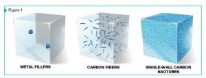
Part of the solution is specifying in the 106 to 109 ohm range. The other part is new flooring additives that create effective conductive networks at lower loading rates. Single-wall carbon nanotubes, for example, can achieve compliance with ANSI/ESD S20.20 at loading rates of 0.1 percent (Figure 1). Due to their unique properties, floors using these materials are not subject to hot spots and provide architects and specifiers with greater control over floor color and finish.
As more flooring manufacturers and installers replace existing additives with newer ones and specifiers better understand the conductivity levels required to safely comply with ANSI/ESD S20.20 resistance-to-ground values, the industry will be better positioned to meet the growing demand for ESD control flooring.
![]() [3]Brandon Atwood is the technical sales director for OCSiAl. He spent over 20 years in the advanced materials industry, and the last four with OCSiAl. He is a graduate of the University of Cincinnati.
[3]Brandon Atwood is the technical sales director for OCSiAl. He spent over 20 years in the advanced materials industry, and the last four with OCSiAl. He is a graduate of the University of Cincinnati.
- [Image]: https://www.constructionspecifier.com/wp-content/uploads/2020/09/ESD1.jpg
- [Image]: https://www.constructionspecifier.com/wp-content/uploads/2020/09/Screen-Shot-2020-09-15-at-12.02.42-PM.jpg
- [Image]: https://www.constructionspecifier.com/wp-content/uploads/2020/09/BrandonAtwood.jpg
Source URL: https://www.constructionspecifier.com/achieving-compliance-with-ansi-esd-s20-20/