Achieving increased envelope performance
In its 2005 Handbook of Fundamentals, the American Society of Heating, Refrigerating, and Air-conditioning Engineers (ASHRAE) use the parallel flow equation #11 in Chapter 23 when calculating the average R-value of a wall that includes multiple wall components. It incorporates each of the parallel thermal paths in conjunction with their relative R-values and percentage of wall construction.
Using this equation, the average R-value of a simple 2.4-m (8-ft) square wood frame wall consisting of 12-mm (½-in.) exterior sheathing, 89 mm (3.5-in.) wood studs at 406 mm (16 in.) on center (oc), fiberglass batt insulation and 12-mm gypsum board is reduced from R-13.1 in the stud spaces to R-11.5 for the average over the entire wall. This represents a 12 percent reduction in the calculated average R-value from that of the insulated stud spaces.
When an additional R-5 of continuous insulation is added on the exterior of the sheathing, the resulting R-values are 18.1 at the stud space, with an average R-16.8 for the entire wall. This represents a reduction of just seven percent between the two.
While the addition of continuous insulation on the building exterior improves the wall’s thermal performance, it significantly complicates the design and installation. Rigid insulation is typically non-structural, which means it requires the inclusion of additional bracing, or a second layer of structural sheathing in the wall construction. Some extruded polystyrene (XPS) board insulation has low permeability to water vapor, which may reduce vapor transmission through the wall. The inclusion of low-permeability wall components may reduce the wall’s capacity to dry, resulting in prolonged moisture accumulation within the wall.
A further complication caused by the addition of a continuous layer of insulation on the framing’s exterior is the introduction of different layers of insulation with different thermal properties. This makes the location of the dewpoint within the wall construction more difficult to calculate. To understand the wall’s thermal performance as it relates to vapor drive, hygrothermic calculations should be conducted by the designer to ensure it conforms with ASHRAE 160-2009, Design Criteria for Moisture Control in Buildings. This can be done with hygrothermic software such as Wärme und Feuchte Instationär (WUFI).
Air leakage
Unintentional air infiltration or exfiltration through the exterior envelope can have serious effects on the building’s performance and occupant comfort and health. Since air leakage passing through the envelope is not conditioned or filtered by the HVAC system, it can introduce pollutants and allergens into the building, along with unwanted drafts or odors. The effectiveness of the mechanical system may also be reduced as it is forced to compensate for the introduction of uncontrolled amounts of unconditioned air into the building.
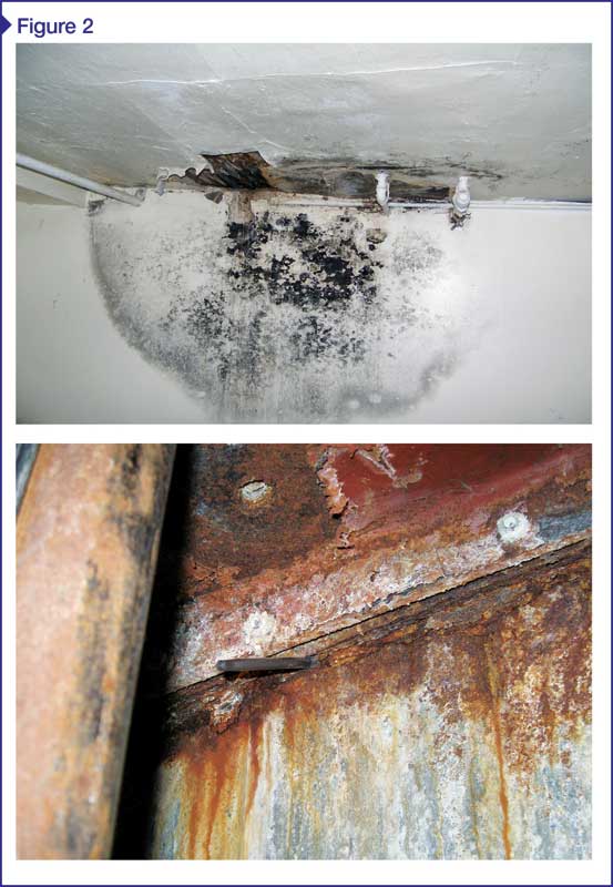
Air leakage is not only a source of energy loss for the building, but it can also transport large amounts of water into the building envelope. During periods of warm, wet weather, air leakage can introduce humid outdoor air into the building. In cold, dry weather, warm, moist indoor air may leak into cold envelope cavities. Either way, condensation can occur within the structure, resulting in a concentration of water in some locations that can facilitate mold growth or rot, or accelerate corrosion (Figure 2).
Differential pressure between the air on the building’s interior and exterior causes leakage. This condition can be brought about by wind, stack effect, or fan pressure caused by the mechanical system. During windy periods, air infiltration can occur on the windward side of a building where there is a slightly higher air pressure, and exfiltrate on the leeward side.

The stack effect is most prominent in taller buildings where warm air rises within the building during cold weather, thereby creating a slightly higher air pressure at the upper floors and a slightly lower pressure at the lower floors. The reverse effect occurs during warmer weather. This effect can be often felt when opening a swinging lobby door in a tall building. In the summer, the door may be slightly ajar due to increased positive pressure at the building base, while in the winter it may be more difficult to open.
Mechanical equipment itself within the building can create a lower pressure within the building, which can contribute to air infiltration. Bathroom and kitchen exhaust fans, laboratory exhaust hoods, chimneys, or reduced intakes on make-up air fans can all contribute to lower interior air pressure. At a given time, any of these causes may be taking place alone or in any combination of all three sources, in which case the effects may be cumulative.
Air leakage is controlled with an air barrier in the exterior envelope. An air barrier is a combination of membranes and/or other wall components that, when sealed together, form a continuous system around the entire building envelope resistant to the passage of air. According to Air Barrier Association of America (ABAA), an air barrier material must be:
- durable, since it may be located within the wall construction and must last for the expected life of the structure, or be easily accessible like an elastomeric coating on exposed concrete masonry units (CMU);
- continuous across the entire building envelope, which means each component of the air barrier be sealed to its adjacent components (e.g. tops of walls must be sealed to the roof air barrier, windows must be sealed to the air barrier in the adjacent wall system, and the bottom of the air barrier in the wall must be sealed to the top of the foundation and the floor slab) as shown in Figure 3;
- structurally supported and capable of transferring the differential pressures created by wind, stack effect, or mechanical systems to the building’s structural support system without excessive deflection or displacement; and
- impermeable to air penetration up to a given performance level.
In the United States, the performance criteria is a maximum of 0.02 L/s*m2 (0.004 cfm/sf) when tested according to ASTM E2178, Standard Test Method for Air Permeance of Building Materials, at a differential pressure of 75 Pa (1.57 psf). This requirement is reduced for systems such as windows because the code recognizes the joints and other connections within.
Sealing the thermal envelope has been required by many editions of IECC. Past requirements were not specific and only needed joints, seams, and penetrations through the building envelope to be sealed with a durable material such as caulking or weatherstripping. In 2009, requirements were increased to require the verification of air-sealing by either a visual inspection against a detailed checklist or a whole-house pressure test using a blower door in residential construction. The 2012 IECC kept the visual checklist requirements, adding the sealing of access panels between conditioned and un-conditioned spaces and rim joists to the list. (Since 2009, the code has also demanded fireplaces have tight-fitting doors and use outside combustion air.)
Sign up for our weekly newsletter
Architectural materials and methods delivered right to your inbox
- CSI News and Notes: CSI Foundation’s construction camp; CSI spring exam; and more
- CSI News and Notes: CSI’s credentials; CSI conference theme; and more
- To be specific – CSI supports young AECO professionals
- CSI News and Notes: CSI’s foundation scholarships, national conference, and Crosswalk
- CSI News and Notes: AI’s impact; CSI 2024 conference, and more
Products


Read the Latest Issue