Achieving increased envelope performance
The most important change for the 2012 IECC is the requirement for all new construction and additions to be both visually inspected and pressure-tested with the blower door procedure (i.e. ASTM E1827-11, Standard Test Methods for Determining Airtightness or Buildings Using an Orifice Blower Door). The parameters require houses to be much tighter than the previous edition of the code by reducing the allowable air changes per hour (ach) at 50-Pa (1-psf) differential pressure, down from 7 to 5 ach in Zones 1 and 2, and down to 3 ach in Zones 3 to 8. This performance level represents a relatively tight building envelope.
Complications arise at the joints between different materials, such as compatibility issues and constructability problems. To maintain continuity, the air barrier at the top of the wall must be sealed to the air barrier in the roof—therefore, the designer and installer must be aware of the compatibility between these components. For example, asphaltic roof membranes may be incompatible with a spun polyolefin air barrier material that is used on the wall system. While the two materials may not cause either to deteriorate, they may still not adhere well to each another.
Other complications may arise at parapet walls where the optimal path of the air barrier could be through the wall rather than around it. This requires coordination between the air barrier installer and the trade installing the structure of the parapet wall.
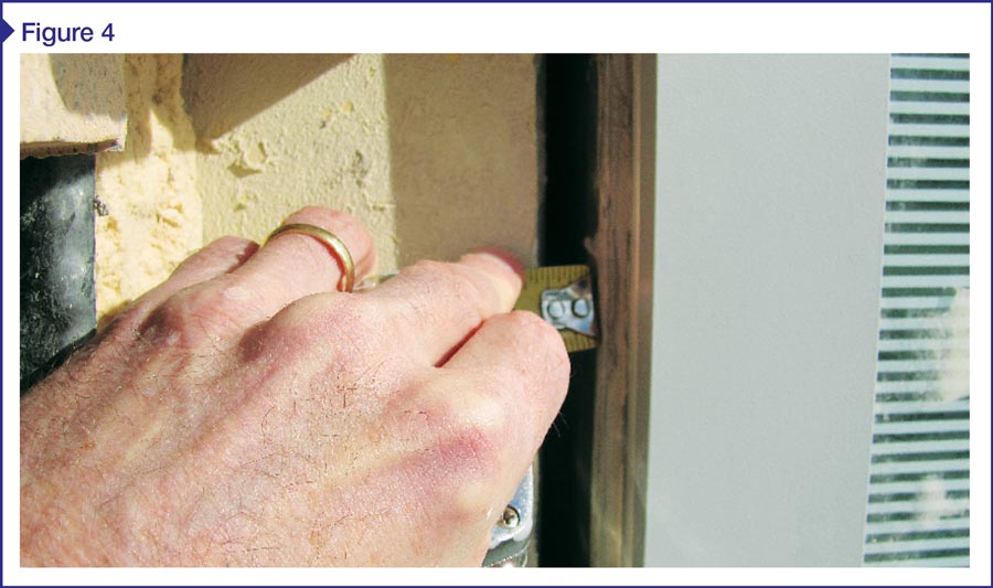
Coordination is also required between the different trades that install adjacent systems. In typical commercial construction practice, windows are installed with a slight gap or shim space between the exterior surface of the window frame and the adjacent framing or masonry (Figure 4). The air barrier must bridge this gap from the opaque wall system to the window frame. The designer must specify (and the installer must coordinate) installation of the air barrier, windows, and opaque wall finishes to ensure the proper tie-ins are in place between the window and the air barrier system in the adjacent wall.
Vapor retarders
Water vapor diffuses directly through permeable building components from warm, moist areas of high vapor pressure to cooler, dryer areas of lower vapor pressure. This occurs at the molecular level in the materials. While leakage of bulk water and air can rapidly transport large amounts of water and moisture through a building envelope, so too can vapor diffusion over time. This can be controlled with vapor retarders.
The effectiveness of a material to control diffusion is measured by its permeability or perms. A perm is defined as the ability to pass one grain of water vapor per hour through one square foot of flat material at one inch of mercury (gr/h*ft²*in.Hg). One grain of water is 1/7000 of a pound or 0.0022 ounces of water.
Vapor retarders are classified based on their permeability. These product types can be separated into four general classes based on their permeance:
- vapor-impermeable: 0.1 perm or less (Class I)—examples include polyethylene film, rubber roof membranes, glass, and metal);
- vapor-semi-impermeable: 1.0 perms or less and greater than 0.1 perm (Class II)—examples include 25 mm (1 in.) or greater of unfaced XPS and oil-based paints, along with vinyl wallcoverings;
- vapor-semi-permeable: 10 perms or less and greater than 1.0 perm (Class III)—examples include oriented strandboard (OSB) and plywood, kraft paper, unfaced expanded polystyrene (EPS), unfaced XPS thinner than 25-mm, fiber-faced polyiso, #30 building paper, and latex-based paints; and
- vapor-permeable: greater than 10 perms—examples include plaster on lath, hardboard, and mineral wool insulation.
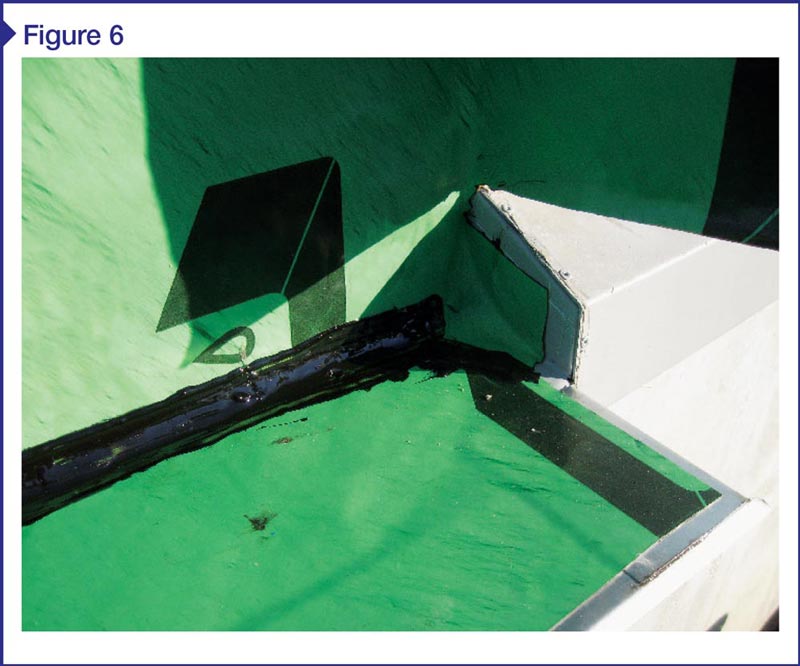
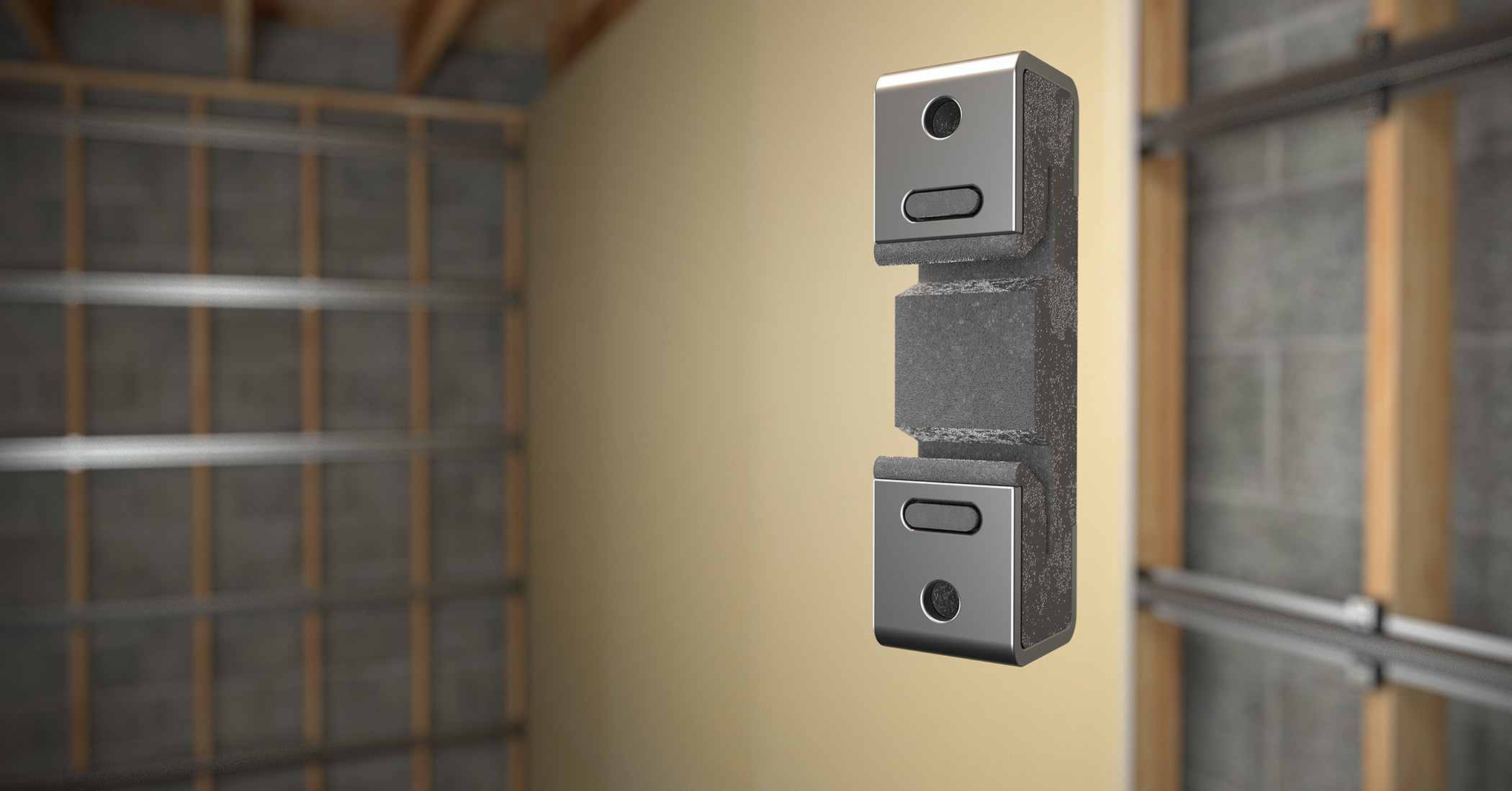
Image courtesy CTL Group
The 2009 IBC allows use of latex paint as a vapor retarder (Class III) based on wall construction and climate zone. It further requires a Class I or II vapor retarder be installed on the warm side of thermal insulation in colder climate zones such as Zones 5, 6, 7, 8, and Marine Zone 4. Although the code specifically calls out the location of the vapor barrier in colder climates, it does not do so for the required perm rating. Different exposures, cladding materials, and interior design conditions can dramatically affect the envelope’s ability to dry.
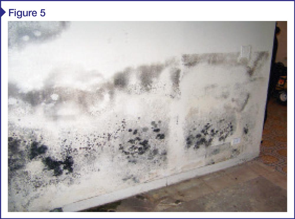
As with the design of the thermal system, hygrothermal software should be used to assist the designer in specifying and locating the vapor barrier within the wall system. Figure 5 shows what may occur when a vapor barrier is on the cool side of insulation in a warm climate.
Design and installation considerations
There are several design considerations that should be addressed when specifying and detailing the four building envelope systems. Each system is interrelated with the other three, and the envelope’s proper function depends on them.
Depending on the materials used (and their location), some of these systems’ functions may be addressed by a single component. For example, many WRBs are also impermeable to vapor and qualify as an air barrier material as well. When specifying these materials, care must be taken to ensure the membrane detailing includes the requirements of all three systems:
- In order to be an effective barrier against bulk water leakage, they must be detailed to control bulk water while directing it to the exterior of the wall via flashings and drainage systems (Figure 6).
- To function properly as an air barrier, they must be:
– continuous;
– sealed to all adjacent air barrier systems with all penetrations sealed;
– durable; and
– capable of transferring the air pressure loading to the structure without excessive deflection and/or movement. - To qualify as a vapor barrier, they must meet the permeability requirements and be located on the proper side of the thermal insulation where the higher vapor drive occurs.
In colder climate zones, when the bulk water barrier is also used as the vapor barrier, it will be located on the insulation’s interior side. This means the insulation may become wet if water is able to penetrate the exterior cladding surface. Many insulation materials dramatically lose their insulating properties if they become saturated with water, requiring the designer to specify and detail the appropriate insulating materials for these conditions.
Air barriers can be made out of permeable or non-permeable materials. If they are the latter, then they may also act as a vapor retarder. To function as an air barrier, the location within the wall system is usually not critical; as a vapor barrier, however, they must be located on the side of the insulation with the higher vapor drive. Otherwise, the vapor barrier may trap moisture within the envelope, causing it to condense, accumulate, and possibly contribute to the premature deterioration of building components.
Brought about by codes and owner demands, the need for increased building envelope performance helps reduce energy consumption and the lifecycle cost of the built environment. However, more than ever, this requires careful design consideration and installation to ensure the assemblies function at their expected levels and avoid future problems.
David Cook, RA, is a principal architect (structural and architectural evaluation) at CTLGroup. He has more than 30 years of experience in commercial and residential construction, project design, structural evaluation, and project management. Cook is a licensed air barrier field auditor, along with a member of American Institute of Architects (AIA), International Facilities Management Association (IFMA), and ASTM E6. He previously served as the superintendent of facilities management for the City of Evanston (Illinois), where he oversaw the construction of the first Leadership in Energy and Environmental Design (LEED) Gold-certified fire station in the state. Cook can be reached at dcook@ctlgroup.com.
Sign up for our weekly newsletter
Architectural materials and methods delivered right to your inbox
- CSI News and Notes: CSI Foundation’s construction camp; CSI spring exam; and more
- CSI News and Notes: CSI’s credentials; CSI conference theme; and more
- To be specific – CSI supports young AECO professionals
- CSI News and Notes: CSI’s foundation scholarships, national conference, and Crosswalk
- CSI News and Notes: AI’s impact; CSI 2024 conference, and more
Products


Read the Latest Issue