Achieving increased envelope performance
by Catherine Howlett | April 1, 2013 12:18 pm
 [1]
[1]by David Cook, RA
Among its many functions, the exterior envelope typically must control the movement of heat, air, bulk water, and water vapor both in and out of a building. Over time, various systems and components have been developed to control this movement.
In a properly functioning envelope, these systems work together to maintain the building’s temperature and allow components to dry quickly if they become wet. While these systems contribute to overall performance, they also contribute to the complexity of the envelope design and sensitivity to error.
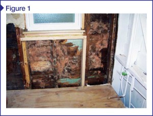
Recent editions of the model codes have increased requirements for thermal insulation, and heightened the base level of acceptable performance for air barriers and vapor retarders. Increasing energy costs have also caused building owners to demand better performance. If one of an envelope’s systems is improperly designed or installed, the increased performance of the other systems may reduce the resulting envelope’s capacity to dry. This may heighten the potential for problems to occur (Figure 1).
An exterior envelope usually contains the following four systems:
- thermal insulation to control the movement of heat through the envelope;
- air barrier to control air leakage through the exterior envelope;
- bulk water-resistant barrier (WRB) to prevent uncontrolled water leakage into the building; and
- vapor retarder to reduce moisture diffusion through the building envelope components.
 [2]
[2]Images courtesy CTLGroup
Preventing uncontrolled bulk water leakage into a building has long been recognized by the model codes, which contain verbiage addressing this requirement. While bulk water penetration remains a common problem, the causes associated with this construction anomaly are fairly well understood. Moreover, the code bodies have made little to no changes regarding this subject. Therefore, this article does not detail components associated with the control of bulk water (except as they pertain to the other three systems).
Concentrating on the thermal, air barrier, and vapor retarder systems, this article details recent changes in the International Building Code (IBC) or the International Energy Conservation Code (IECC), along with potential design and installation problems. In referencing the code, the prescriptive requirements will be noted because they offer the clearest comparison of the changes—the alternative compliance options are unlimited, but the prescriptive requirements serve as their basis.
Thermal performance
Heat moves through a building envelope through both opaque and transparent portions. While code requirements for thermal performance of fenestration products—including solar heat gain coefficient (SHGC), visible transmittance (VT), and U-value of the glazing—have increased, this article concentrates on opaque areas of the building envelope.
Thermal energy’s movement through the opaque envelope portions are resisted by insulation. All materials have some thermal properties, but some are better insulators than others. Thermal insulation material is measured by its R-value—the inverse of thermal conductance, which is the number of Btus transmitted through a 305-mm (12-in.) square piece of 25-mm (1-in.) thick material, with one degree of difference between the two sides of the material. In the United States, the R-value is measured in Imperial units, therefore it is an abbreviation of hr*sf*F/Btu.
The higher the R-value, the better its resistance to heat flow. For example, 25 mm (1 in.) of concrete has an R-value of 1, while 25 mm of foil-faced polyisocyanurate (polyiso) rigid insulation has an R-value of 7.2. Un-faced fiberglass batt insulation has an R-value of 3.14 per inch. Since R-values are additive, the resulting R-value of 89 mm (3.5 in.) of fiberglass batt insulation in a 2×4 stud wall cavity would be approximately R-11. When the R-values of the exterior sheathing and interior gypsum board are added, the R-value of an unclad 2×4 frame wall can approach R-13, depending on the sheathing material and thickness.
From 2006 to 2012, IECC increased the required R-value in most portions of the building envelope in all zones. For example, the requirement for above-grade wall insulation in Zone 6 went from R-19 to R-21 +R-5. The +5 is a requirement for continuous insulation (ci) with a rating of R-5 on the exterior of the framing.
The call for ci in the building envelope has made a large impact on exterior wall design and construction. The requirement was added to help eliminate thermal bridging caused by framing members or other wall components extending through the insulation in a conventionally insulated wall cavity. Thermal bridging was shown to reduce the cladding’s overall thermal performance.
In its 2005 Handbook of Fundamentals, the American Society of Heating, Refrigerating, and Air-conditioning Engineers (ASHRAE) use the parallel flow equation #11 in Chapter 23 when calculating the average R-value of a wall that includes multiple wall components. It incorporates each of the parallel thermal paths in conjunction with their relative R-values and percentage of wall construction.
Using this equation, the average R-value of a simple 2.4-m (8-ft) square wood frame wall consisting of 12-mm (½-in.) exterior sheathing, 89 mm (3.5-in.) wood studs at 406 mm (16 in.) on center (oc), fiberglass batt insulation and 12-mm gypsum board is reduced from R-13.1 in the stud spaces to R-11.5 for the average over the entire wall. This represents a 12 percent reduction in the calculated average R-value from that of the insulated stud spaces.
 [3]
[3]When an additional R-5 of continuous insulation is added on the exterior of the sheathing, the resulting R-values are 18.1 at the stud space, with an average R-16.8 for the entire wall. This represents a reduction of just seven percent between the two.
While the addition of continuous insulation on the building exterior improves the wall’s thermal performance, it significantly complicates the design and installation. Rigid insulation is typically non-structural, which means it requires the inclusion of additional bracing, or a second layer of structural sheathing in the wall construction. Some extruded polystyrene (XPS) board insulation has low permeability to water vapor, which may reduce vapor transmission through the wall. The inclusion of low-permeability wall components may reduce the wall’s capacity to dry, resulting in prolonged moisture accumulation within the wall.
A further complication caused by the addition of a continuous layer of insulation on the framing’s exterior is the introduction of different layers of insulation with different thermal properties. This makes the location of the dewpoint within the wall construction more difficult to calculate. To understand the wall’s thermal performance as it relates to vapor drive, hygrothermic calculations should be conducted by the designer to ensure it conforms with ASHRAE 160-2009, Design Criteria for Moisture Control in Buildings. This can be done with hygrothermic software such as Wärme und Feuchte Instationär (WUFI).
Air leakage
Unintentional air infiltration or exfiltration through the exterior envelope can have serious effects on the building’s performance and occupant comfort and health. Since air leakage passing through the envelope is not conditioned or filtered by the HVAC system, it can introduce pollutants and allergens into the building, along with unwanted drafts or odors. The effectiveness of the mechanical system may also be reduced as it is forced to compensate for the introduction of uncontrolled amounts of unconditioned air into the building.
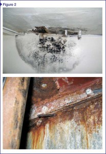
Air leakage is not only a source of energy loss for the building, but it can also transport large amounts of water into the building envelope. During periods of warm, wet weather, air leakage can introduce humid outdoor air into the building. In cold, dry weather, warm, moist indoor air may leak into cold envelope cavities. Either way, condensation can occur within the structure, resulting in a concentration of water in some locations that can facilitate mold growth or rot, or accelerate corrosion (Figure 2).
Differential pressure between the air on the building’s interior and exterior causes leakage. This condition can be brought about by wind, stack effect, or fan pressure caused by the mechanical system. During windy periods, air infiltration can occur on the windward side of a building where there is a slightly higher air pressure, and exfiltrate on the leeward side.
 [4]
[4]The stack effect is most prominent in taller buildings where warm air rises within the building during cold weather, thereby creating a slightly higher air pressure at the upper floors and a slightly lower pressure at the lower floors. The reverse effect occurs during warmer weather. This effect can be often felt when opening a swinging lobby door in a tall building. In the summer, the door may be slightly ajar due to increased positive pressure at the building base, while in the winter it may be more difficult to open.
Mechanical equipment itself within the building can create a lower pressure within the building, which can contribute to air infiltration. Bathroom and kitchen exhaust fans, laboratory exhaust hoods, chimneys, or reduced intakes on make-up air fans can all contribute to lower interior air pressure. At a given time, any of these causes may be taking place alone or in any combination of all three sources, in which case the effects may be cumulative.
Air leakage is controlled with an air barrier in the exterior envelope. An air barrier is a combination of membranes and/or other wall components that, when sealed together, form a continuous system around the entire building envelope resistant to the passage of air. According to Air Barrier Association of America (ABAA), an air barrier material must be:
- durable, since it may be located within the wall construction and must last for the expected life of the structure, or be easily accessible like an elastomeric coating on exposed concrete masonry units (CMU);
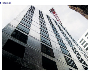
- continuous across the entire building envelope, which means each component of the air barrier be sealed to its adjacent components (e.g. tops of walls must be sealed to the roof air barrier, windows must be sealed to the air barrier in the adjacent wall system, and the bottom of the air barrier in the wall must be sealed to the top of the foundation and the floor slab) as shown in Figure 3;
- structurally supported and capable of transferring the differential pressures created by wind, stack effect, or mechanical systems to the building’s structural support system without excessive deflection or displacement; and
- impermeable to air penetration up to a given performance level.
In the United States, the performance criteria is a maximum of 0.02 L/s*m2 (0.004 cfm/sf) when tested according to ASTM E2178, Standard Test Method for Air Permeance of Building Materials, at a differential pressure of 75 Pa (1.57 psf). This requirement is reduced for systems such as windows because the code recognizes the joints and other connections within.
Sealing the thermal envelope has been required by many editions of IECC. Past requirements were not specific and only needed joints, seams, and penetrations through the building envelope to be sealed with a durable material such as caulking or weatherstripping. In 2009, requirements were increased to require the verification of air-sealing by either a visual inspection against a detailed checklist or a whole-house pressure test using a blower door in residential construction. The 2012 IECC kept the visual checklist requirements, adding the sealing of access panels between conditioned and un-conditioned spaces and rim joists to the list. (Since 2009, the code has also demanded fireplaces have tight-fitting doors and use outside combustion air.)
 [5]
[5]The most important change for the 2012 IECC is the requirement for all new construction and additions to be both visually inspected and pressure-tested with the blower door procedure (i.e. ASTM E1827-11, Standard Test Methods for Determining Airtightness or Buildings Using an Orifice Blower Door). The parameters require houses to be much tighter than the previous edition of the code by reducing the allowable air changes per hour (ach) at 50-Pa (1-psf) differential pressure, down from 7 to 5 ach in Zones 1 and 2, and down to 3 ach in Zones 3 to 8. This performance level represents a relatively tight building envelope.
Complications arise at the joints between different materials, such as compatibility issues and constructability problems. To maintain continuity, the air barrier at the top of the wall must be sealed to the air barrier in the roof—therefore, the designer and installer must be aware of the compatibility between these components. For example, asphaltic roof membranes may be incompatible with a spun polyolefin air barrier material that is used on the wall system. While the two materials may not cause either to deteriorate, they may still not adhere well to each another.
Other complications may arise at parapet walls where the optimal path of the air barrier could be through the wall rather than around it. This requires coordination between the air barrier installer and the trade installing the structure of the parapet wall.
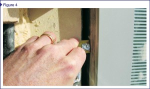
Coordination is also required between the different trades that install adjacent systems. In typical commercial construction practice, windows are installed with a slight gap or shim space between the exterior surface of the window frame and the adjacent framing or masonry (Figure 4). The air barrier must bridge this gap from the opaque wall system to the window frame. The designer must specify (and the installer must coordinate) installation of the air barrier, windows, and opaque wall finishes to ensure the proper tie-ins are in place between the window and the air barrier system in the adjacent wall.
 [6]
[6]Vapor retarders
Water vapor diffuses directly through permeable building components from warm, moist areas of high vapor pressure to cooler, dryer areas of lower vapor pressure. This occurs at the molecular level in the materials. While leakage of bulk water and air can rapidly transport large amounts of water and moisture through a building envelope, so too can vapor diffusion over time. This can be controlled with vapor retarders.
The effectiveness of a material to control diffusion is measured by its permeability or perms. A perm is defined as the ability to pass one grain of water vapor per hour through one square foot of flat material at one inch of mercury (gr/h*ft²*in.Hg). One grain of water is 1/7000 of a pound or 0.0022 ounces of water.
Vapor retarders are classified based on their permeability. These product types can be separated into four general classes based on their permeance:
- vapor-impermeable: 0.1 perm or less (Class I)—examples include polyethylene film, rubber roof membranes, glass, and metal);
- vapor-semi-impermeable: 1.0 perms or less and greater than 0.1 perm (Class II)—examples include 25 mm (1 in.) or greater of unfaced XPS and oil-based paints, along with vinyl wallcoverings;
- vapor-semi-permeable: 10 perms or less and greater than 1.0 perm (Class III)—examples include oriented strandboard (OSB) and plywood, kraft paper, unfaced expanded polystyrene (EPS), unfaced XPS thinner than 25-mm, fiber-faced polyiso, #30 building paper, and latex-based paints; and
- vapor-permeable: greater than 10 perms—examples include plaster on lath, hardboard, and mineral wool insulation.
 [7]
[7]Image courtesy CTL Group
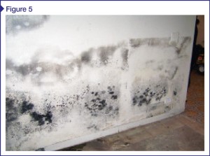
The 2009 IBC allows use of latex paint as a vapor retarder (Class III) based on wall construction and climate zone. It further requires a Class I or II vapor retarder be installed on the warm side of thermal insulation in colder climate zones such as Zones 5, 6, 7, 8, and Marine Zone 4. Although the code specifically calls out the location of the vapor barrier in colder climates, it does not do so for the required perm rating. Different exposures, cladding materials, and interior design conditions can dramatically affect the envelope’s ability to dry.
As with the design of the thermal system, hygrothermal software should be used to assist the designer in specifying and locating the vapor barrier within the wall system. Figure 5 shows what may occur when a vapor barrier is on the cool side of insulation in a warm climate.
Design and installation considerations
There are several design considerations that should be addressed when specifying and detailing the four building envelope systems. Each system is interrelated with the other three, and the envelope’s proper function depends on them.
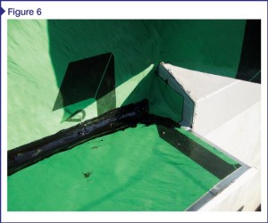
Depending on the materials used (and their location), some of these systems’ functions may be addressed by a single component. For example, many WRBs are also impermeable to vapor and qualify as an air barrier material as well. When specifying these materials, care must be taken to ensure the membrane detailing includes the requirements of all three systems:
- In order to be an effective barrier against bulk water leakage, they must be detailed to control bulk water while directing it to the exterior of the wall via flashings and drainage systems (Figure 6).
- To function properly as an air barrier, they must be:
– continuous;
– sealed to all adjacent air barrier systems with all penetrations sealed;
– durable; and
– capable of transferring the air pressure loading to the structure without excessive deflection and/or movement. - To qualify as a vapor barrier, they must meet the permeability requirements and be located on the proper side of the thermal insulation where the higher vapor drive occurs.
In colder climate zones, when the bulk water barrier is also used as the vapor barrier, it will be located on the insulation’s interior side. This means the insulation may become wet if water is able to penetrate the exterior cladding surface. Many insulation materials dramatically lose their insulating properties if they become saturated with water, requiring the designer to specify and detail the appropriate insulating materials for these conditions.
Air barriers can be made out of permeable or non-permeable materials. If they are the latter, then they may also act as a vapor retarder. To function as an air barrier, the location within the wall system is usually not critical; as a vapor barrier, however, they must be located on the side of the insulation with the higher vapor drive. Otherwise, the vapor barrier may trap moisture within the envelope, causing it to condense, accumulate, and possibly contribute to the premature deterioration of building components.
Brought about by codes and owner demands, the need for increased building envelope performance helps reduce energy consumption and the lifecycle cost of the built environment. However, more than ever, this requires careful design consideration and installation to ensure the assemblies function at their expected levels and avoid future problems.
David Cook, RA, is a principal architect (structural and architectural evaluation) at CTLGroup. He has more than 30 years of experience in commercial and residential construction, project design, structural evaluation, and project management. Cook is a licensed air barrier field auditor, along with a member of American Institute of Architects (AIA), International Facilities Management Association (IFMA), and ASTM E6. He previously served as the superintendent of facilities management for the City of Evanston (Illinois), where he oversaw the construction of the first Leadership in Energy and Environmental Design (LEED) Gold-certified fire station in the state. Cook can be reached at dcook@ctlgroup.com.
- [Image]: http://www.constructionspecifier.com/wp-content/uploads/2013/04/bigstock-Office-Building-3335385.jpg
- [Image]: http://www.constructionspecifier.com/wp-content/uploads/2013/04/barriers_Figure1.jpg
- [Image]: http://www.constructionspecifier.com/wp-content/uploads/2013/04/barriers_Figure2.jpg
- [Image]: http://www.constructionspecifier.com/wp-content/uploads/2013/04/barriers_Figure3.jpg
- [Image]: http://www.constructionspecifier.com/wp-content/uploads/2013/04/barriers_Figure4.jpg
- [Image]: http://www.constructionspecifier.com/wp-content/uploads/2013/04/barriers_Figure5.jpg
- [Image]: http://www.constructionspecifier.com/wp-content/uploads/2013/04/barriers_Figure6.jpg
Source URL: https://www.constructionspecifier.com/achieving-increased-envelope-performance/