Adjacent precast box beam bridges
Beam fabrication and instrumentation
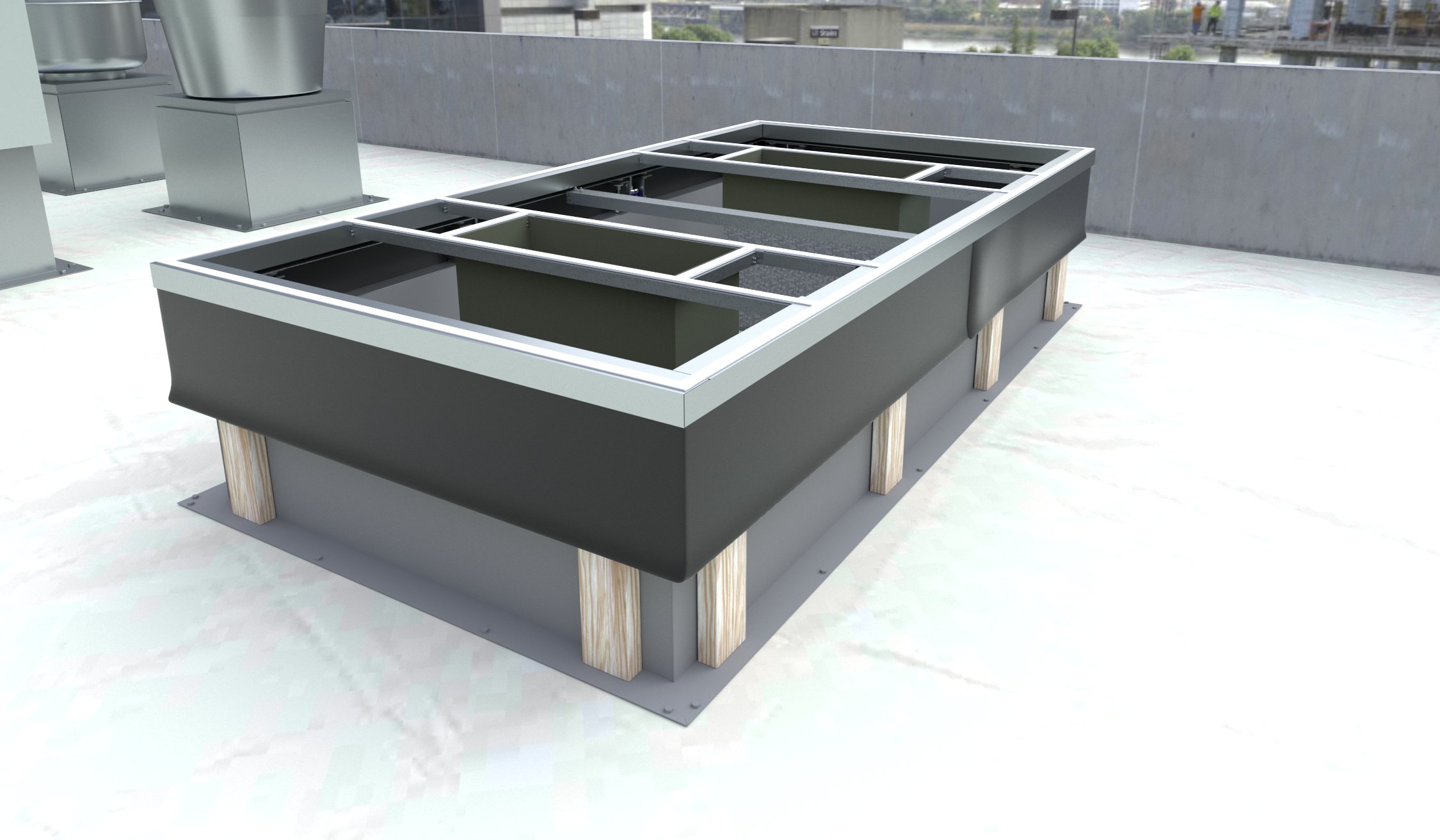
In May 2014, the box beams were fabricated in a precast and prestressed concrete manufacturing facility in Kalamazoo, Michigan. The typical box beam form was used, except the shear key shape was modified using wood. For exterior Beams 1 and 7, the shear key modification was used only on the inside face of the beams. (For reference, the beams were numbered one to seven—from left to right—while facing the forward abutment.) For the remaining interior beams, the shear key form was used on both sides. The wood form for the new shear keys can be seen in Figure 3.
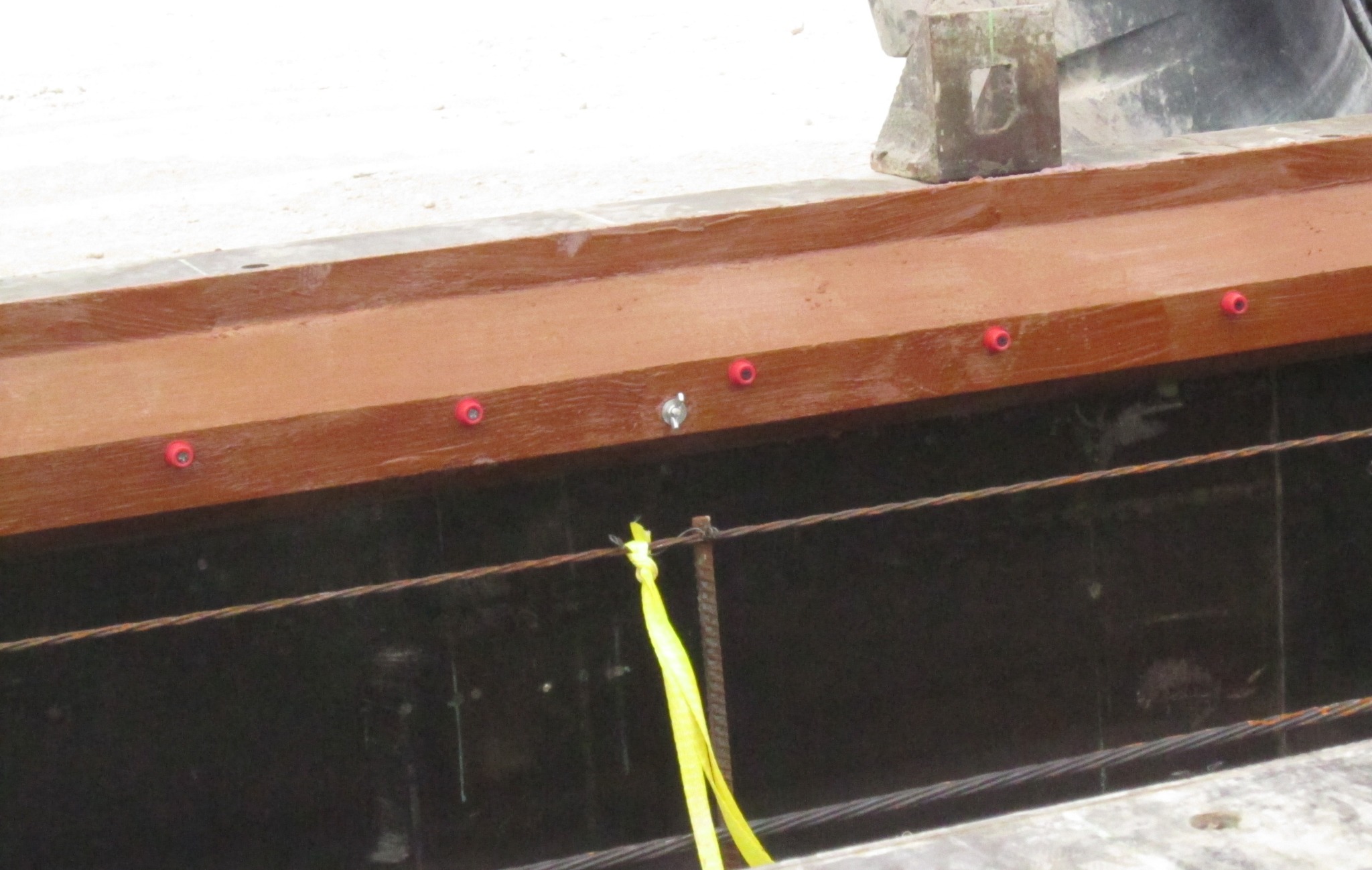
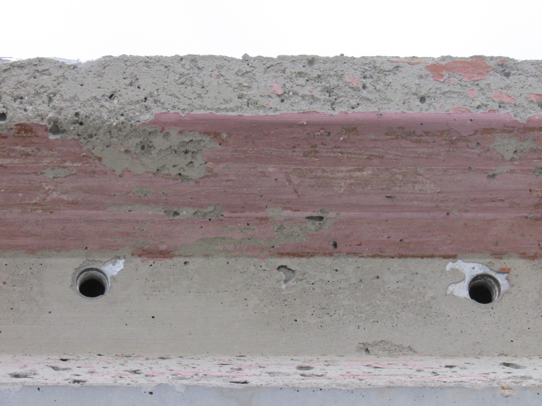
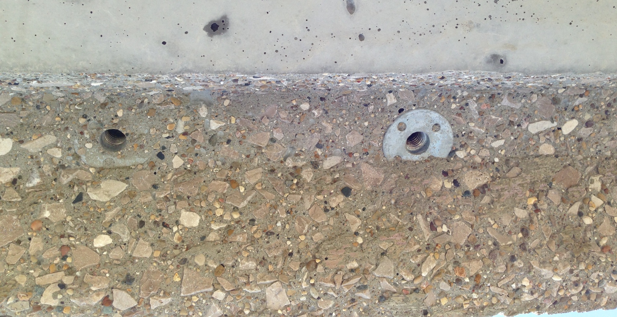
The form was coated with a retarder and the embedded ends of the dowel bar assemblies (with the female threaded ends) were placed on the red plastic tabs. Figure 4 shows the final installation. Figures 5 and 6 show the shear key upon removal of the box beam from the forms before and after power-washing, respectively. The end result was a rough shear key surface with exposed aggregate that enhanced the bond between the beams and UHPC.
The first three box beams were instrumented with vibrating wire strain gages embedded in the beams, and on the dowel bars. A total of 15 vibrating wire strain gages, VW4200, were used in the three beams. Five strain gages were used in each beam to monitor the strain in the longitudinal and transverse directions. Two vibrating wire strain gages, one in the top flange and one in the bottom, were placed longitudinally at the quarter span. Three vibrating wire strain gages, one longitudinal and one transverse in the top flange, and one longitudinal in the bottom flange, were used at mid-span. The bottom gages were positioned between strands and the top gages mounted between the shear reinforcement.
Figure 7 shows a longitudinal, vibrating-wire-strain gage positioned in the form between the strands at the bottom flange. The wiring for the instrumentation was run to extra plastic drain forms and sealed with tape. This allowed access to the wiring after beams were delivered to the bridge site. Figure 8 shows the gages on the top flange. The wiring for this instrumentation was run in between the closed-cell extruded polystyrene (XPS) void inserts and into a drain form.

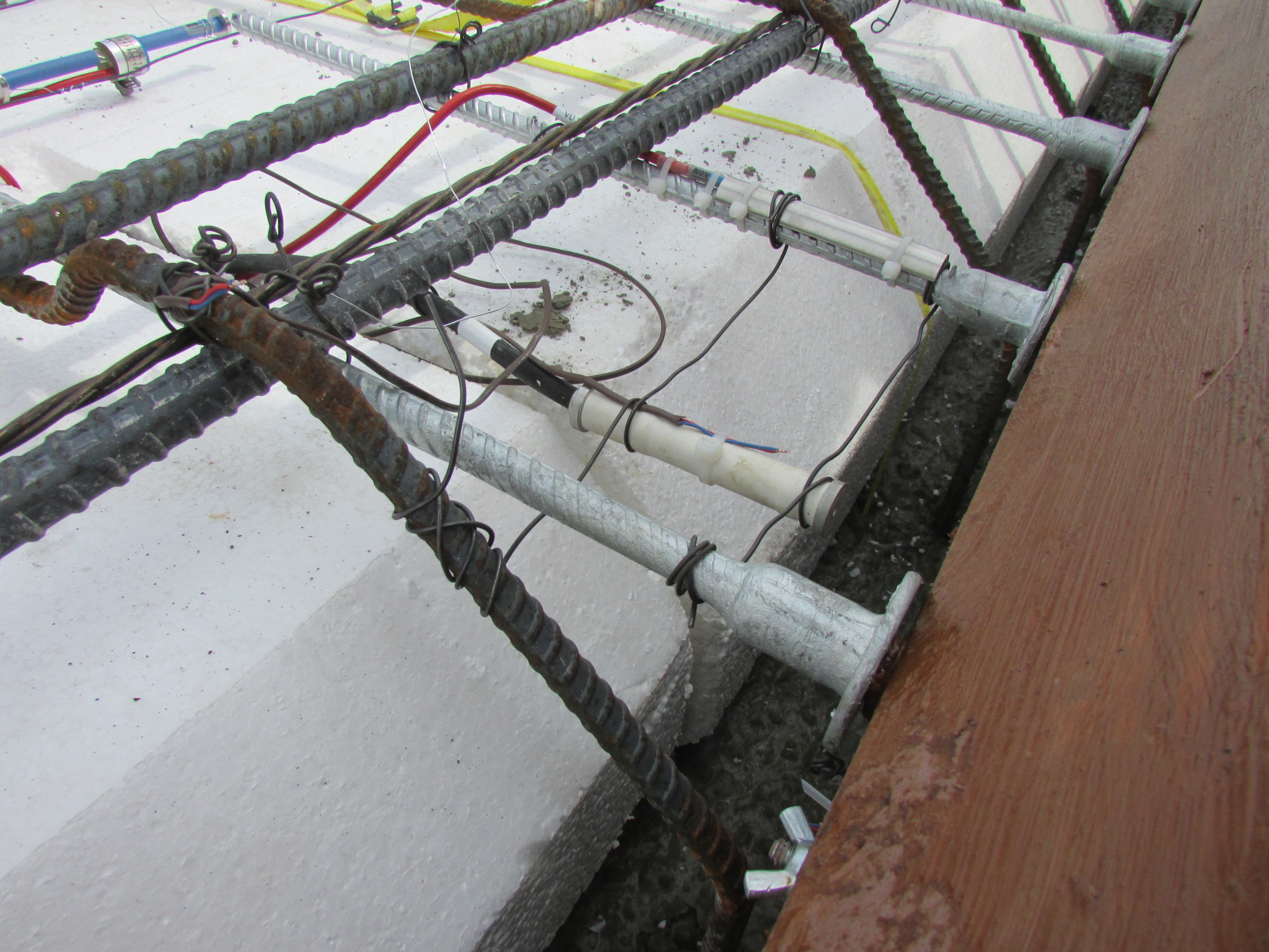
The embedded ends of the dowel bars in each beam were instrumented using vibration wire strain gages (i.e. VW4150), with one at the quarter span and one at mid-span. The gages were installed at a distance of 51 mm (2 in.) from the threaded end. Beams 1, 2, and 3 had the instrumented dowel bars on right side of the cross section. The installed instrumented dowel bar can be seen in Figure 9, and includes a protective shield to avoid damage from the concrete. Beam 3 was also instrumented with four thermocouples throughout the depth to measure the temperature gradients (Figure 10).

Sign up for our weekly newsletter
Architectural materials and methods delivered right to your inbox
- CSI News and Notes: CSI Foundation’s construction camp; CSI spring exam; and more
- CSI News and Notes: CSI’s credentials; CSI conference theme; and more
- To be specific – CSI supports young AECO professionals
- CSI News and Notes: CSI’s foundation scholarships, national conference, and Crosswalk
- CSI News and Notes: AI’s impact; CSI 2024 conference, and more


Read the Latest Issue