Adjacent precast box beam bridges
by Katie Daniel | July 29, 2015 11:18 am
 [1]
[1]By Eric Steinberg, PhD, PE, Ali Semendary, and Kenneth Walsh, PhD
For years, adjacent prestressed concrete box-beam bridges have been employed for short and medium spans—two-thirds of all state Department of Transportations (DOTs) use them. While they are popular due to ease of construction and low profile, cracks in the longitudinal grouted joints between adjacent beams have often been observed. This can lead to leakage through the joint, accelerating corrosion of reinforcement and diminishing load transfer. New use of ultra-high-performance concrete (UHPC) grout may provide a solution to this problem.
The poor transverse connection of the shear keys is often the main cause of these longitudinal cracks. Different solutions have been suggested to reduce this cracking, including the study of shear key configurations and grouting materials in a full-scale box beams. In that research, a typical small-depth shear key was tested either with non-shrinkage grout or with epoxy, and a mid-depth shear key was tested with non-shrinkage grout. The small-depth shear key with non-shrinkage grout was cast in the November of 1998, with only minor shrinkage cracks observed after inspection.
Prior to load testing in January 1999, cracks were observed in the key that were attributed to the cold winter climate. The strain gages embedded in the beams and shear keys recorded a large jump in strain when the temperature reached −18 C (0 F). When the beams were tested under cyclic load, the temperature induced cracks propagated. However, it was difficult to determine whether the cracks were caused by the loading or cold temperature as the test was performed outside.
The mid-depth shear key was tested in May, and the shear key cracked after just one week. The temperature was also determined to be the main cause for the cracking.
The author concluded the vertical temperature gradient in the beams, rather than the ambient temperature, was the main cause for the cracking. Daily temperature variation caused deflections that led some joints to open and others to close. As the beams did not sit perfectly on the abutments, the movement created sufficient strains to cause cracking in the shear key.
Epoxy was also used as a grouting material in the shear key, and no cracks were observed due to temperature or loading. However, epoxy is undesirable to use because of the large difference in the thermal expansion coefficients between epoxy and concrete. The mid-depth shear key was constructed with non-shrinkage grout. The cracking was reduced because the throat was not grouted, which helped to reduce the temperature stresses. The recommendations were to use transverse post-tensioning to limit joint movement, neutral axes shear keys with non-grouted throats, or full-depth shear keys.
In-service adjacent box beam bridges in Michigan were inspected to evaluate changes in the design of side-by-side box beam bridges. The design changes were full-depth grouted shear keys, a high level of transverse post-tensioning, and a cast-in-place deck with seven-day moist curing.
It was determined the Michigan box beam bridges still experienced longitudinal reflective cracks irrespective of age. One of the bridges inspected while still under construction showed reflected cracks developed within three days after grouting before post-tensioning was applied, and continued to crack even after post-tensioning. When the bridge was inspected after three weeks, cracks were observed in every shear key of the bridge. It was determined the cracking was a result of de-bonding between the shear key and adjacent box beams. The authors concluded a redesign should be employed.
Potential with UHPC
One way to address the longitudinal cracking in adjacent box-beam bridges is to use an improved grouting material with enhanced tensile and bond strength. Ultra-high-performance concrete represents a new class of concrete that has high strength and durability characteristics. It has been defined as a cementitious composite material composed of an optimized gradation of granular constituents, a water-to-cementitious materials (w/cm) ratio less than 0.25, and a high percentage of discontinuous internal fiber reinforcement.
The mechanical properties of UHPC include compressive strength greater than 21.7 ksi (150 MPa) and sustained post-cracking tensile strength greater than 0.72 ksi (5 MPa). The material has a discontinuous pore structure that reduces liquid ingress, significantly enhancing durability compared to conventional concrete.
Due to its properties, UHPC has been investigated as a grouting material in connection joints. The continent’s first bridge relying on this application is a skewed 24.38-m (80-ft) single span overhead bridge in Rainy Lake, Ontario. UHPC was also employed elsewhere in Ontario with a non-corrosive glass-fiber-reinforced polymer (GFRP) rebar in the longitudinal and transverse joints of the three-span side-by-side Eagle River Bridge. Additional GFRP rebar was also added to the transverse joint to assist with load transfer. The UHPC was placed successfully and the required strength was provided after the curing period.
One of this article’s co-authors has investigated the behavior of a pair of box beams under live and temperature gradient loading using finite element modeling. Two shear key configurations (partial and full depth) containing dowel bars spaced at 102 mm (4 in.) on center (oc) were employed to connect the box beams. The partial-depth shear key model was calibrated using the laboratory results from two adjacent box beams tested at the Turner Fairbank Highway Research Center (TFHRC).
The full-depth shear key was modeled using the same parameters as the partial-depth key as no experimental data was available at the time of modeling. The maximum principle stresses in
the shear keys and dowel bars were investigated. The results showed the maximum principle stresses increased in the partial-depth shear key after applying the temperature gradients. However, there was a decrease in the maximum principle stresses for the full-depth key. Also, shear keys exhibited larger principle tensile stresses as dowel bar spacing increased, although the partial-depth shear key exhibited less tensile stresses than the full-depth key. The principle stresses in the dowel bars increased with the inclusion of temperature gradients for both shear keys. Both shear key configurations experienced differential deflection less than 0.51 mm (0.02 in.).
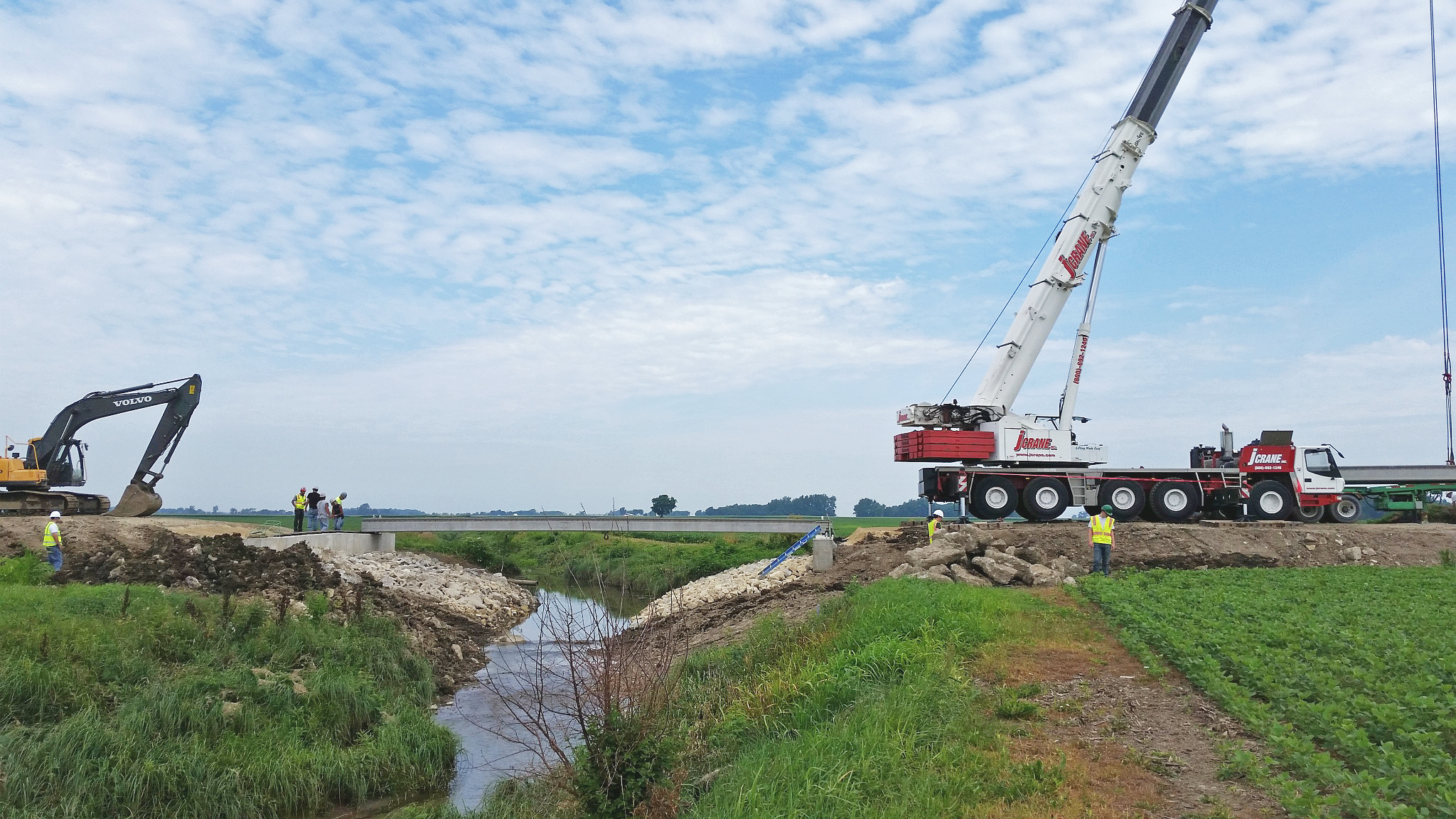
Based on the experimental results from the TFHRC and the finite element modeling, a UHPC shear key with the same shape and with 102-mm (4-in.) dowel bar spacing was used in the design of a bridge constructed last summer in Fayette County, Ohio. To understand the behavior of this bridge with a new longitudinal shear key joint, it was instrumented in multiple locations. The bridge was tested and monitored to investigate its behavior due to live and environmental loads.
 [2]
[2]Bridge description
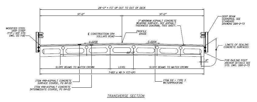
The bridge was constructed on Sollars Road, near the town of Washington Court House. The bridge consists of seven adjacent box beams and has a total length of 18.6 m (61 ft) and width of 8.5 m (28 ft). Each box beam is 1.22 m (4 ft) wide and 0.53 m (1 3⁄4 ft) deep (Figure 1).
Twenty-eight 13-mm (1⁄2-in.) diameter seven-wire low relaxation strands with a 1860 MPa (270 ksi) ultimate strength were used for prestressing in each box beam. The mild reinforcement (used primarily for shear) had 414 MPa (60 ksi) yield strength. The box beams have a diaphragm at each end that is 0.84 m (2 3⁄4 ft) in length. The ends of the beams rest on two bearing pads, and are connected to the abutments using a tie rod. The bridge did not have transverse tie rods which is common practice in Ohio. Further, neither transverse post-tensioning nor a composite deck were utilized.
The bridge incorporated the new shear key design developed and tested at the TFHRC. The new design consisted of using UHPC as the grouting material with equally spaced dowel bars in each joint. The new shear key was larger than the typical shear key. It employed used dowel bars that were threaded into the beams and staggered at 102-mm (4-in.) spacing.
The testing at TFHRC involved connecting two box beams together and applying a concentrated load. The results show the new design was sufficient to make the bridge behave as a unit, and no cracks were recorded in the shear keys even after numerous loading cycles. Finite element modeling, along with a parametric analysis, was also performed for the tested beams and it was shown larger spacing of the dowel bars could be used. However, the same dowel spacing was employed in the bridge in an attempt to replicate the laboratory conditions.
 [3]
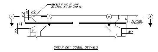
[3]The dowel bar system had two parts, where the first part is embedded in the beam 460 mm (18 in.) and contained a female threaded end. The part embedded in the shear key had a length of 120 mm (4 3⁄4 in.) and had a male threaded end, allowing it to be screwed into the part embedded in the beam. Similar shear key designs have been used in bridges in Ontario, although no data exists to quantify the performance of this type of shear key design. Figure 2 shows details of the shear key.
 [4]
[4]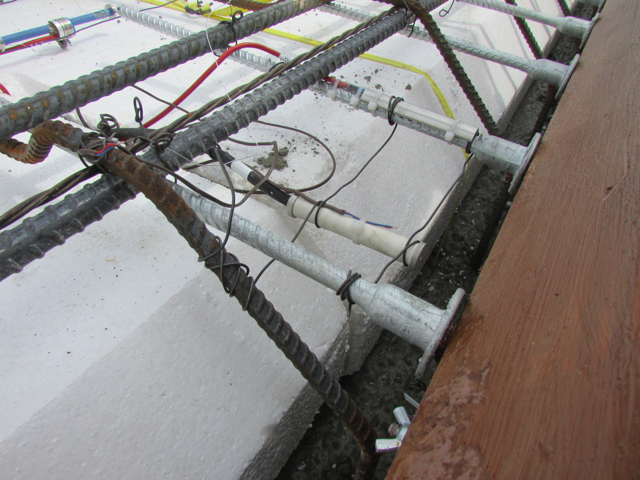 [5]
[5]
Beam fabrication and instrumentation
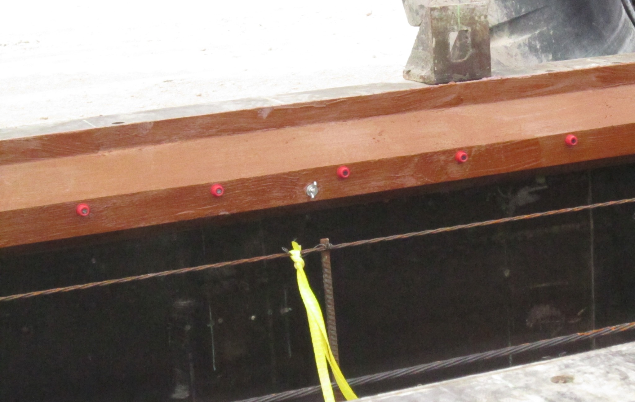
In May 2014, the box beams were fabricated in a precast and prestressed concrete manufacturing facility in Kalamazoo, Michigan. The typical box beam form was used, except the shear key shape was modified using wood. For exterior Beams 1 and 7, the shear key modification was used only on the inside face of the beams. (For reference, the beams were numbered one to seven—from left to right—while facing the forward abutment.) For the remaining interior beams, the shear key form was used on both sides. The wood form for the new shear keys can be seen in Figure 3.
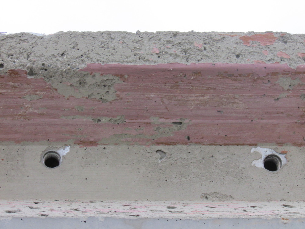
The form was coated with a retarder and the embedded ends of the dowel bar assemblies (with the female threaded ends) were placed on the red plastic tabs. Figure 4 shows the final installation. Figures 5 and 6 show the shear key upon removal of the box beam from the forms before and after power-washing, respectively. The end result was a rough shear key surface with exposed aggregate that enhanced the bond between the beams and UHPC.
 [6]
[6]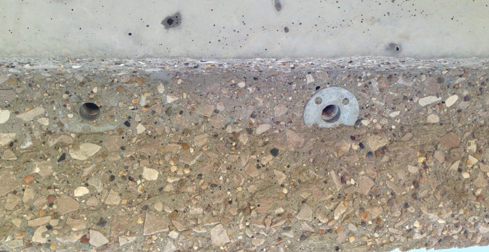 [7]
[7]
The first three box beams were instrumented with vibrating wire strain gages embedded in the beams, and on the dowel bars. A total of 15 vibrating wire strain gages, VW4200, were used in the three beams. Five strain gages were used in each beam to monitor the strain in the longitudinal and transverse directions. Two vibrating wire strain gages, one in the top flange and one in the bottom, were placed longitudinally at the quarter span. Three vibrating wire strain gages, one longitudinal and one transverse in the top flange, and one longitudinal in the bottom flange, were used at mid-span. The bottom gages were positioned between strands and the top gages mounted between the shear reinforcement.
Figure 7 shows a longitudinal, vibrating-wire-strain gage positioned in the form between the strands at the bottom flange. The wiring for the instrumentation was run to extra plastic drain forms and sealed with tape. This allowed access to the wiring after beams were delivered to the bridge site. Figure 8 shows the gages on the top flange. The wiring for this instrumentation was run in between the closed-cell extruded polystyrene (XPS) void inserts and into a drain form.
 [8]
[8]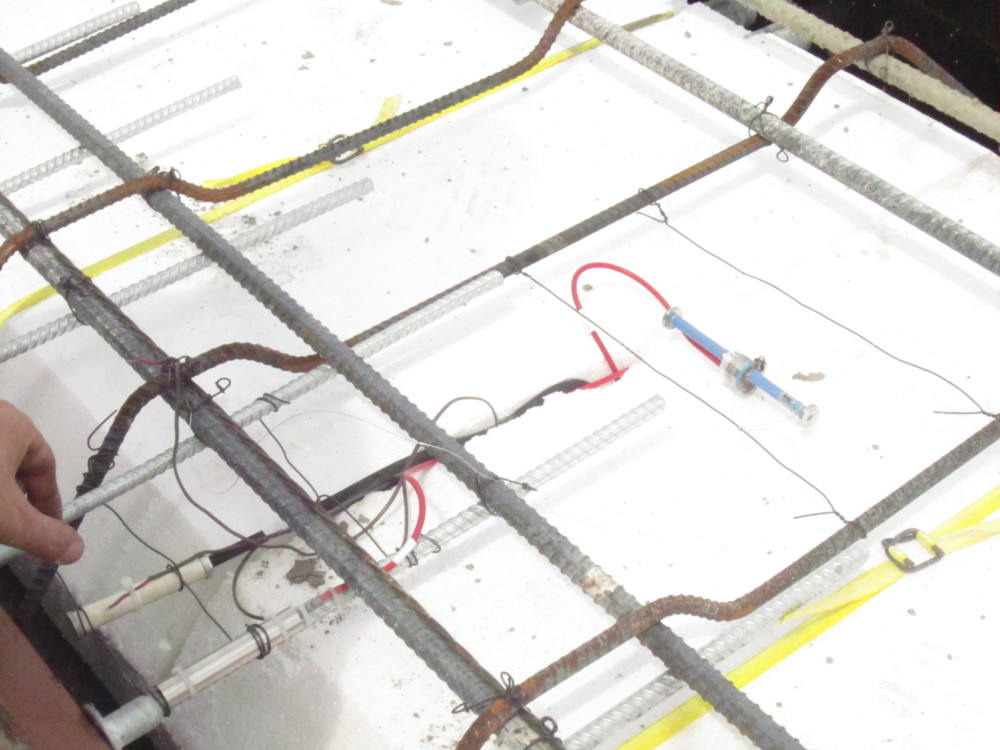 [9]
[9]The embedded ends of the dowel bars in each beam were instrumented using vibration wire strain gages (i.e. VW4150), with one at the quarter span and one at mid-span. The gages were installed at a distance of 51 mm (2 in.) from the threaded end. Beams 1, 2, and 3 had the instrumented dowel bars on right side of the cross section. The installed instrumented dowel bar can be seen in Figure 9, and includes a protective shield to avoid damage from the concrete. Beam 3 was also instrumented with four thermocouples throughout the depth to measure the temperature gradients (Figure 10).
 [10]
[10]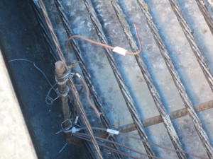 [11]
[11] [12]
[12]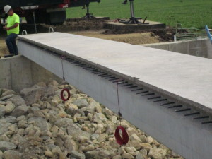 [13]
[13]The first beam was cast on May 7, 2014. The following day, the prestressed strands were cut and the box beam was lifted from the form and loaded onto a truck. While the beam was on the truck, power-washing with water was used to obtain the exposed aggregate surface in the shear key. The beam was then moved to the yard for curing. The same procedure was used for the remaining beams.
One May 28, the contractor began to remove the old bridge and the new bridge’s foundations and abutments were constructed. On July 12, the box beams were transported to the site. Six vibrating wire strain gages were installed on six dowel bar inserts (male threaded end).
 [14]
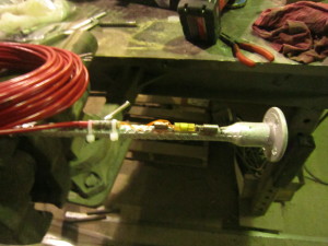
[14]Each dowel bar was instrumented with one VW4150 gage at distance of 38 mm (1 1⁄2 in.) from threaded end (Figure 11). While the beam was on the truck, the dowel bars were screwed into the embedded part of the dowel bar assembly. Instrumented dowel bars were installed to the left side of cross section of Beams 2, 3, and 4. Two instrumented dowel bars were used in each beam, one at the quarter span and one at mid-span (Figure 12).
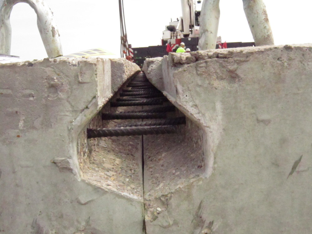
The beams were then moved from the truck and set on the abutments using a crane. Each end of each beam rested on bearing pads on the abutments. Additionally, one positioning vertical dowel bar at each end of each beam was placed through the beam into the abutment. The forward abutment vertical dowel bars allowed for expansion by using a joint sealer around the dowels. The rear abutment vertical dowel bars were grouted into place to create a fixed condition. Figure 13 provides a view of the shear key with dowels after the beam placement has taken place.
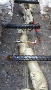
On July 16, the three shear keys between Beams 1 through 4 were instrument with vibrating wire strain gages. Six vibrating wire strain gages, VW 4202, were placed in the transverse direction because these gages had a short length that allowed them to fit transversely in the shear key (Figure 14). Each shear key was instrumented with one transverse gage at the quarter span and one transverse strain gage at mid-span. Four vibrating wire strain gages, VW4200, were used in the longitudinal direction (Figure 15). Shear Keys 1 and 3 were instrumented with one gage at the quarter span and one gage at mid-span.
 [15]
[15]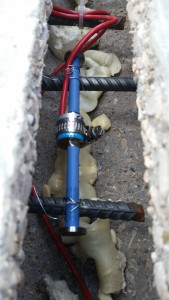 [16]
[16]After installation, the excess expandable filler material between beams was removed and the joints were covered with plywood, except for larger openings at the quarter points along the shear key.
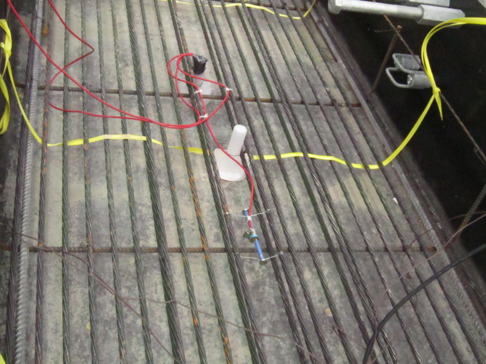
On July 17, the shear key joints were cast using UHPC. Two mixers were used to properly mix the material before it was moved to the joints in wheelbarrows and placed into chimneys made of plastic buckets located at the larger joint openings (Figure 16). The UHPC flowed into the joints, and the filling of the joints was ensured by the hydraulic head in the chimneys. Instrumentation was connected to data-acquisition systems to monitor the bridge as the UHPC cured.
On July 22, the plywood forms were removed from the joints. No cracks were observed from inspection of the shear keys. On July 24, a waterproofing membrane was installed atop the bridge as work continued on the approaches. The bridge was paved with an asphalt wearing surface on August 5. The following day, frames were set up underneath the bridge at the quarter-span and mid-span (Figure 17).
 [17]
[17] [18]
[18]On August 7, a total of 16 strain gages, seven linear variable differential transformers (LVDTs), and three thermocouples were installed to monitor the bridge. Seven electrical resistance strain gages (i.e. WFLM-60-11-2 LT) were glued to the bottom of the beams in the longitudinal direction at mid-span to measure the strain from truck loading.
 [19]
[19]Seven vibrating wire strain gages (i.e. KM- 100B), were installed in gage brackets that had been epoxied to the beam bottoms. They were placed in the longitudinal direction at mid-span to measure the strain from temperature loading; two were also epoxied on two columns of the frame in the vertical direction to measure the strain frame from temperature.
A total of three thermocouples were used, one on the left column of the frame, one on the right column of the frame, and one on the bottom of Beam 4.
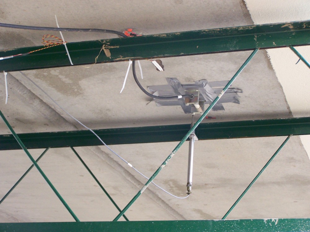
The seven LVDTs were affixed to the frame using brackets. The frame was used as a reference surface from which the bridge response was measured. Figure 18 shows the LVDT mounted to the frame along with a KM-100B mounted in a bracket (temporarily held in place with duct tape as the epoxy sets), and the electrical resistance strain gage (white).
Bridge testing
On August 8, two loaded trucks were used to load-test the bridge. The weights of the trucks were 249.5 and 237.5 kN (56.1 and 53.4 kip). Four static load configurations were used in the tests, and the trucks were positioned to obtain the maximum moment at mid-span. The first and second load configurations consisted of a single truck placed in the left and right lanes, respectively. The third load configuration consisted of two trucks placed side-by-side, and the forth load configuration consisted of both trucks placed back-to-back in the left lane (Figure 19).
 [20]
[20]Data was collected using two data-acquisition systems. The exterior instrumentation, which included seven WFLM-60-11-2 LT gages and seven LVDTs, was connected to Acquisition System 1. All embedded instrumentation, KM-100Bs, and thermocouples were connected to Acquisition System 2, which was programed to take readings every 15 minutes. (Acquisition System 1 took readings during the time the trucks were stopped on the bridge.)
After finishing the static truck testing, dynamic testing was conducted by driving one truck at speeds of 8, 16, 24, 40, and 48 km/h (5, 10, 15, 25, and 30 mph), and data was collected. After finishing the dynamic truck test, the seven LVDTs were connected to Acquisition System 2 for long-term monitoring.
On December 15, five LVDTs and three thermocouples were added to the bridge. Joints 4, 5, and 6 were instrumented with three LVDTs. Two brackets were used to install the LVDTs across the joints in the transverse direction at mid-span. Two LVDTs were installed at the two ends of Beam 7 to monitor the girder movement during temperature changes. One thermocouple was installed on Beam 1 and another on Beam 7 to monitor the temperature on both sides of the bridge. One thermocouple was installed on the bottom of Beam 3 to monitor the temperature at this location, in addition to the four thermocouples already embedded in the beam.
Conclusion
The construction process started with prior bridge removal on May 28, 2014. The new bridge was opened to traffic on August 13, less than three months from closing the road (which included performing research on the new shear key design). The relative rapid reopening of the bridge emphasizes the reason for preferring the adjacent box beam bridge for local owners. Longitudinal cracks did not appear in the longitudinal shear key joints for this bridge, which have been observed in the early age of some non-shrinkage grout shear keys in other bridges. The superior mechanical properties and durability of UHPC appear to make it suitable to use as grout material in the shear keys of adjacent prestressed concrete box beam bridges. The bridge continues to be monitored with instrumentation and data is being processed for further evaluation on bridge performance.
If the joints on this bridge continue to perform well, designs containing larger dowel spacing may be able to be utilized for cost savings without hindering performance. The overall improved joint performance may lead to renewed use and longer design lives for adjacent prestressed concrete box beam bridges.
Eric Steinberg, PhD, PE, is a professor in civil engineering at Ohio University. He served as assistant chair from 1997 to 2005 and is a registered engineer in the State of Ohio. A member of the American Concrete Institute (ACI), American Society of Civil Engineers (ASCE), and Precast/Prestressed Concrete Institute (PCI), he is a board member of Ohio’s Research Initiative for Locals, and has served as an expert witness in the field of structural engineering. Steinberg is an active member of PCI’s Student Education and Bridge Committees, and has been faculty advisor for student organizations of ASCE and Structural Engineers Association of Ohio (SEAO). He can be reached via e-mail at steinber@ohio.edu[21].
Ali Semendary, MS, is a graduate research assistant at Ohio University and a PhD candidate in its Department of Civil Engineering. He obtained his bachelor’s and master’s degrees from Babylon University in Iraq. Semendary’s research interests are in the area of structural engineering. He can be reached via e-mail at as295111@ohio.edu[22].
Kenneth Walsh, PhD, is an assistant professor at Ohio University’s Department of Civil Engineering and the director of the school’s Experimental Engineering Mechanics Laboratory. His research interests are in the area of structural engineering with emphasis on computational methods of analysis. Walsh has published multiple research articles in academic journals including Structural Engineering, Journal of Earthquake Engineering, and Engineering Vibration. A member of the American Society of Civil Engineers (ASCE) and the American Institute of Steel Construction (AISC), he can be reached via email at walshk@ohio.edu[23].
- [Image]: http://www.constructionspecifier.com/wp-content/uploads/2015/07/File-Opener-Image_edited.jpg
- [Image]: http://www.constructionspecifier.com/wp-content/uploads/2015/07/19.jpg
- [Image]: http://www.constructionspecifier.com/wp-content/uploads/2015/07/18-copy.jpg
- [Image]: http://www.constructionspecifier.com/wp-content/uploads/2015/07/17.jpg
- [Image]: http://www.constructionspecifier.com/wp-content/uploads/2015/07/16.jpg
- [Image]: http://www.constructionspecifier.com/wp-content/uploads/2015/07/15.jpg
- [Image]: http://www.constructionspecifier.com/wp-content/uploads/2015/07/14.jpg
- [Image]: http://www.constructionspecifier.com/wp-content/uploads/2015/07/13.jpg
- [Image]: http://www.constructionspecifier.com/wp-content/uploads/2015/07/12.jpg
- [Image]: http://www.constructionspecifier.com/wp-content/uploads/2015/07/11.jpg
- [Image]: http://www.constructionspecifier.com/wp-content/uploads/2015/07/10.jpg
- [Image]: http://www.constructionspecifier.com/wp-content/uploads/2015/07/9.jpg
- [Image]: http://www.constructionspecifier.com/wp-content/uploads/2015/07/8.jpg
- [Image]: http://www.constructionspecifier.com/wp-content/uploads/2015/07/7.jpg
- [Image]: http://www.constructionspecifier.com/wp-content/uploads/2015/07/6.jpg
- [Image]: http://www.constructionspecifier.com/wp-content/uploads/2015/07/5.jpg
- [Image]: http://www.constructionspecifier.com/wp-content/uploads/2015/07/4.jpg
- [Image]: http://www.constructionspecifier.com/wp-content/uploads/2015/07/3.jpg
- [Image]: http://www.constructionspecifier.com/wp-content/uploads/2015/07/2.jpg
- [Image]: http://www.constructionspecifier.com/wp-content/uploads/2015/07/1.jpg
- steinber@ohio.edu: mailto:steinber@ohio.edu
- as295111@ohio.edu: mailto:as295111@ohio.edu
- walshk@ohio.edu: mailto:walshk@ohio.edu
Source URL: https://www.constructionspecifier.com/adjacent-precast-box-beam-bridges/