

Wall-to-footing transition and footer termination
A more complex, and probably the most common, condition experienced in below-grade waterproofing involves the junction where the below-grade vertical wall meets the building’s footing (i.e. the horizontal base).
The wall and footing are constructed in separate concrete pours, creating a cold-pour joint. This junction is one of the most critical details in the waterproofing system. As such, prior to the junction being formed, a bentonite-based expanding waterstop is placed where the footing and wall will meet. The waterstop serves as a last line of defense, should the balance of the waterproofing system be damaged post-application or improperly installed.
Following the creation of the wall-to-footing junction, a flexible one- or two-component, 100-percent solids non-sag polyurethane sealant—compatible with the membrane—is placed at the inside corner that is created, creating a minimum 19-mm (¾-in.) face cant bead between the wall and footing.
This cant bead serves two purposes. First, it provides an additional layer of protection to seal the cold joint, inboard of the membrane, so a layer of protection remains if the membrane is accidentally damaged prior to or during backfill. Second, applying any sheet-type product into a 90-degree inside turn can be challenging at best. The potential for “bridging” to occur—where the membrane transitions from the wall to the footing prior to reaching the bottom of the wall—is great. This void or “bridge” is a weak point where a puncture can easily occur during or prior to backfill, and behind which water can laterally migrate. Thus, by creating this polyurethane sealant cant bead, a challenging 90-degree turn is changed into two much more manageable 45-degree turns (i.e. wall to cant bead and then cant bead to footer).
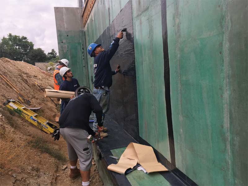
Following the application of the polyurethane sealant cant bead, a waterproofing membrane detail strip measuring 229-mm wide is applied (Figure 3). This provides a double layer of the self-adhering sheet waterproofing membrane over this critical joint. The self-adhering sheet waterproofing membrane is then installed, extending out onto the footer past the detail strip.
As a final step, self-adhered waterproofing membrane footing terminations must always be addressed to not expose the substrate-to-membrane seam directly to any hydrostatic (e.g. water) head pressures. A rubberized-asphalt mastic or a flexible one- or two-component, 100-percent solids non-sag polyurethane sealant is applied, as a final layer of protection, on top of the field waterproofing membrane along the entire seam where the self-adhered waterproofing membrane terminates on the footing and on all waterproofing membrane seams, extending 305 mm (12 in.) in both directions from the corner.
Pipe penetrations
A pipe penetration through a concrete foundation wall is a bit more challenging for the waterproofing system. Consider that, essentially, a hole is purposely being put in a below-grade wall, but there is still a need to prevent water from entering the structure. By taking the same system approach to this condition, a waterproof result can still be achieved.
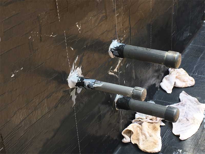
If the pipe is installed through the concrete forms before the concrete is poured it should be wrapped with an expanding bentonite waterstop (Figure 4).
After the concrete wall is poured and the forms are removed, a polyurethane sealant cant is installed around the pipe, to eliminate the 90-degree turn out onto the pipe. This is similar to the wall-to-footer example described earlier. Then, a 229-mm strip of self-adhered waterproofing membrane, cut halfway through—like a “hula skirt”—is wrapped around the pipe, with the “skirt legs” extending out onto the wall.
The waterproofing membrane flashing is terminated with a pipe clamp and covered with mastic or sealant. Lastly, the field waterproofing membrane is installed and cut tight to the pipe penetration, detailed with mastic or sealant and protected with a drainage composite.
Waterproofing termination at grade
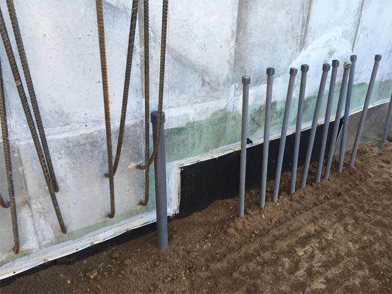
The termination of the self-adhered rubberized-asphalt sheet membrane at grade is very important to the long-term life of the waterproofing system. A rigid metal (aluminum or stainless steel) termination bar is employed (Figure 5).
Since typical waterproofing systems are not ultraviolet (UV) stable and have to be terminated 102 to 152 mm (4 to 6 in.) below grade, a cementitious waterproofing assembly should be employed to protect the area of the wall between the waterproofing termination and grade. The self-adhered rubberized-asphalt waterproofing system is installed up to a determined point and will be permanently secured using a metal termination bar attached at 150 mm
on center (o.c.). Rubberized-asphalt mastic or a polyurethane sealant will be used to cover the termination area. Then the drainage composite will be installed to protect the waterproofing system.
While these examples illustrate just a few of the typical conditions one will encounter on a commercial waterproofing project, they highlight the importance of a “waterproofing system” approach. This approach ensures the best product or accessory is employed on each step and each product is compatible with the one that follows.
Harold Hays is the building envelope systems technical services manager for North America for MAPEI Corporation. He has been in the construction industry for more than 38 years, including 18 years in the architectural field and 17 years in the commercial waterproofing and air and vapor barrier market segments. Hays provides design and installation-related technical service to architects, consultants, building owners, and contractors as well as assists with new product development projects. He can be reached at hhays@mapei.com.

