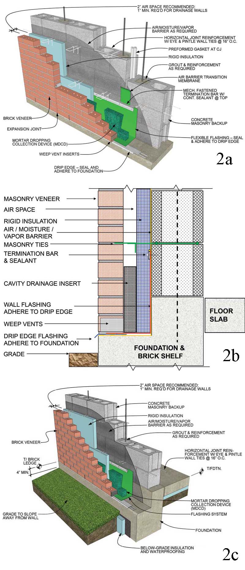
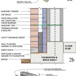
Exposed flashing is generally metal, and installed to prevent moisture from entering the wall are predominantly found at roof/wall interfaces or at other locations adjacent to another exterior façade material or element. Flashings are installed to re-direct water to the exterior and are attached to the vertical masonry backup, preferably along with a termination bar and sealant (Figure 2). The flashing is then installed along the horizontal plane where water exits through weep vents.
The next code requirement—flashing at perimeters of exterior openings or locations where water could enter the wall—is sometimes misinterpreted or confused with air/moisture/vapor barrier requirements. Generally, through-wall flashing is installed at vertical windows and doors (perimeter jambs), as these locations are not typically considered spots where water can enter and flashing can be detailed and connected to effectively “drain water.” However, window and door jambs, and other similar type openings, often require a moisture management transition membrane integral with the air/moisture/vapor barrier.
There is only one location in the code where a ‘drip’ is code-required, as defined in 1405.4:
Flashing with projecting flanges shall be installed on both sides of and the ends of ends of copings, under sills, and continuously at projecting trim.
This definition applies to metal exposed copings and exposed flashings over wood or other exterior trim elements.
In 1405.4, the 2012 IBC Code Commentary notes exposed flashing drips prevent the re-entry of moisture below the flashing. Figure 1405.4(5) illustrates this concept, but the details do not indicate the industry requirement that flashing be sealed to the surface below. This assists at preventing moisture from reentering the wall system and flashings that extend to the face of masonry have performed successfully for years. The code and commentary also indicate other acceptable practices.
Base of wall: Masonry above grade
Flashing at the base of walls, near grade and with exposed flashing drip edges, are highly visible and noticeable, especially at building entrances, exterior patios, sloping grades, and at prominent elevations. Normal tolerance in the concrete shelf and foundation can further cause aesthetic detraction by creating inconsistent drip-edge overhangs.
Figure 2 illustrates a typical wall section in which the exterior masonry veneer begins 100 to 150 mm (4 to 6 in.) above grade on the foundation or brick shelf (as shown in 2b and 2c). These details offer the most protection for the masonry veneer as it is not in contact with soils or landscaped material, and is less susceptible to staining (i.e. the aforementioned ‘rising damp’). Masonry materials that are elevated, as shown in these details and illustrated in Figure 3, are also protected from snow removal and general maintenance at walks, paved areas, and lawn and landscaped areas.
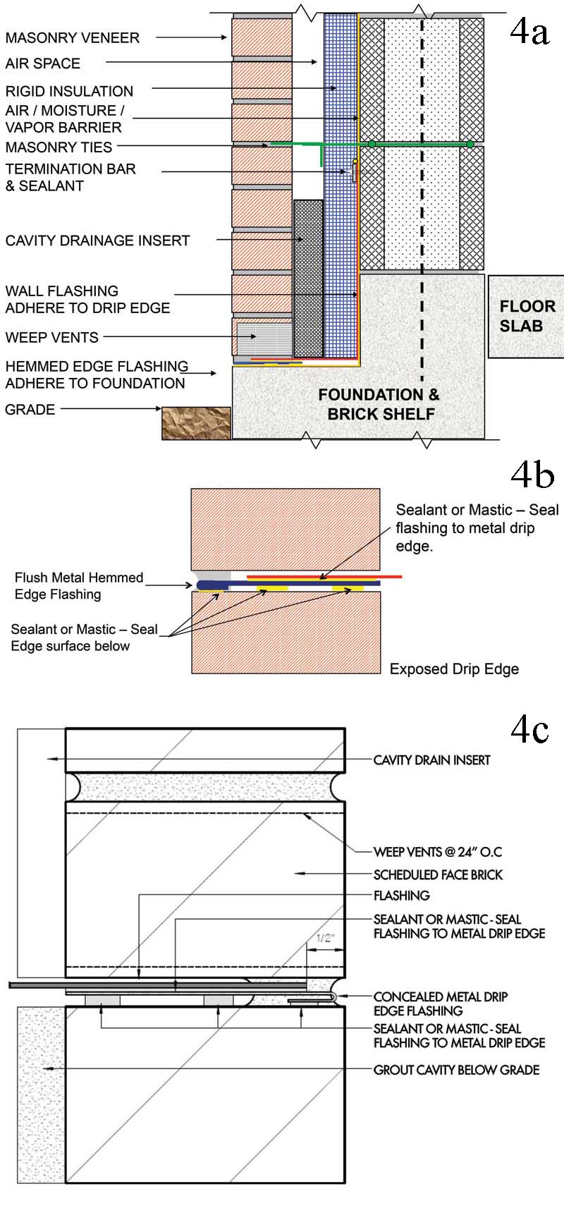
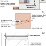
While Figure 2 shows a typical exposed metal drip edge, flush hemmed-edge metal flashing (which terminates at the exterior face of the veneer) has recently been used to eliminate the aesthetic exposure of the drip edge (Figure 4).
The critical requirements for using hemmed-edge flashing are:
- The metal flashing must have a hemmed edge—approximately 12 to 20 mm (½ to ¾ in.) to provide rigidity of the metal flashing and protect the installers and public from sharp edges.
- The hemmed-edge flashing must be sealed and adhered to concrete or the surface below to prevent water from entering under the flashing system. This detail is made possible and durable thanks to new butyl and hybrid butyl-silicones that remain flexible, are less likely to dry out over time, and do not ‘drool.’
- The hemmed edge must be flush with the exterior face of the veneer.
- The continuation wall flashing (either membrane or metal if two-piece) must be sealed and adhered to the top of metal flashing with two or three beads of sealant as shown in Figure 4. This is critical, even with drip flashing, to prevent water from migrating under the flashing.
- A brick shelf 100 to 200 mm (4 to 8 in.) lower than the top of foundation and floor slab is recommended, but not required. This acts as redundancy protection—should water enter the system, it will not enter the building at the floor level.
- Installing the horizontal flashing leg, drip edge, or flush edge at a slight bevel to the exterior assists in directing moisture to the outside of the wall assembly. This is accomplished by mortar wash or other acceptable methods. Sloping the flashing may not be necessary if the horizontal leg is secured and adhered to the surface below to prevent water reentry. The designer has options based on each type of detail.
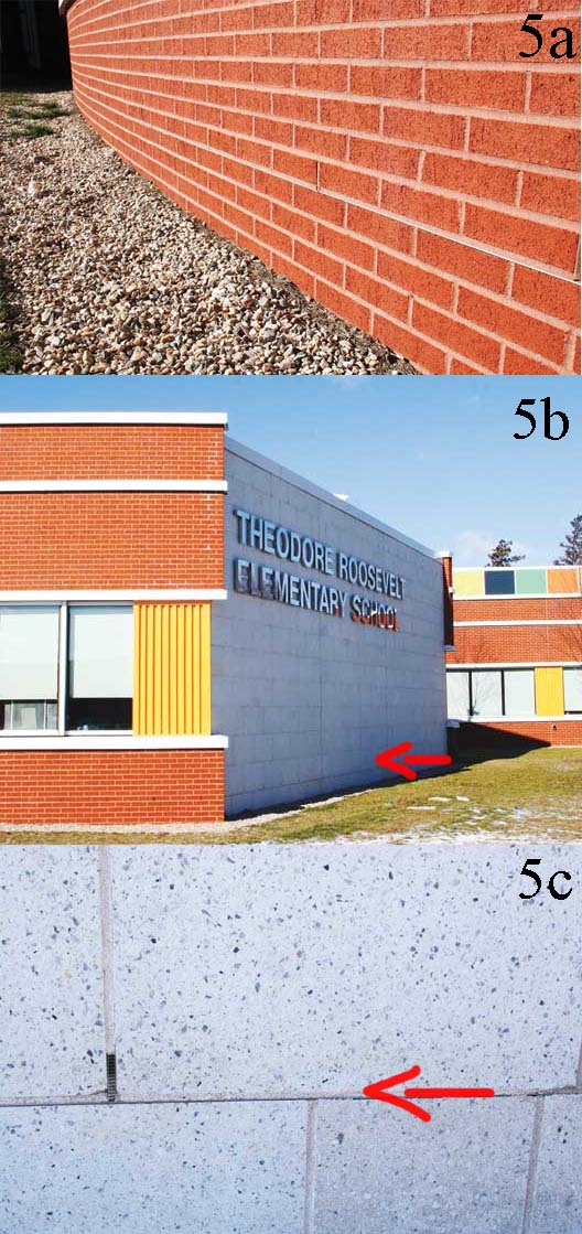
Figure 5 depicts successful results with flush, hemmed- edge flashing.
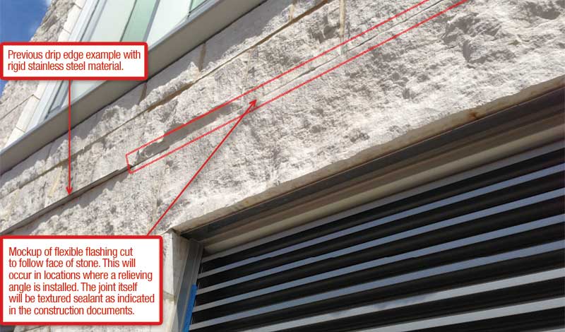
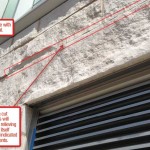
Stainless steel membrane flashings consisting of a thin layer of stainless steel bonded to an adhesive layer are fairly new to the market. They can be cut after installation to follow the contour of the veneer, which is especially useful with split-face stone products (Figure 6). The aesthetics of this detail and care of installation should be agreed on with a mockup panel.


