Amenity roof design challenges: Coordinating waterproofing and drainage with luxury features
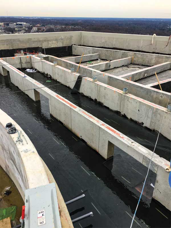
Often, project teams find it is infeasible or impractical to provide dedicated internal drains in each zone. Additionally, as the plumbing and structural engineers coordinate the design of overflow drainage, the waterproofing and stem wall design must incorporate alternative paths for water flow between zones (e.g. discontinuities in stem walls or ‘block-outs’ at the base of the stem walls). Block-outs are a reasonable approach to communicate water between zones, but only when the waterproofing design strategy places the membrane continuously below the stem walls. This is because providing competent four-sided waterproof flashing through the block-out is significantly more workmanship sensitive and likely less reliable in service, if the waterproofing instead extends up and over the stem wall. Placing the waterproofing membrane continuously below the stem walls also has construction schedule benefits (faster drying-in of the structural deck by the waterproofing contractor), but the design team must confirm the membrane is suitable for this purpose, durable, and has a predictable service life comparable to the materials installed above it. Further, each penetration of the vertical reinforcing bars engaging the stem wall to the structural concrete deck requires flashing. However, the flashing operation of round bars is straightforward and it benefits in service from protection by its encasement in cast-in-place concrete. With that said, it is important to coordinate the location of block-outs so they do not coincide with the reinforcing steel.
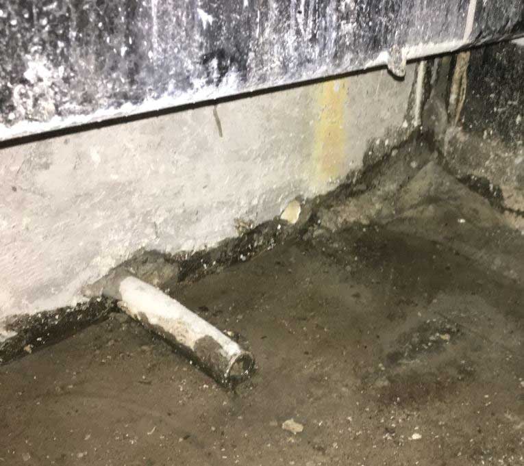
If block-outs or stem wall discontinuities are incorporated, in the interest of limiting the tortured nature of the path between water entry into the interstitial space and the nearest drain (as well as the associated higher risk of water leakage), it is advisable to coordinate the block-out locations and slope of the waterproofing membrane so water never has to travel through more than one block-out on its way to an internal drain. Additionally, the block-outs should be sized and constructed with materials minimizing the likelihood of clogging or impeding water flow in service. In the authors’ experience, approximately 203 mm (8 in.) tall x 203 mm (8 in.) wide block-outs, formed by rigid insulation boards that are removed after curing of the concrete stem wall outperform small polyvinyl chloride (PVC) pipes that are sometimes cast into the bottom of stem walls with the intent of serving as block-outs. Aside from the undesirable clogging tendency of the small pipes, the round section of the pipe result in water ponding on the upslope side of the pipe (Figure 3).
Once the drainage design at the waterproofing level coalesces, or in parallel with this process, coordination with the raised deck drainage must take place. The nature of the raised deck drainage system will initially be driven by the specification of the wearing surface (e.g. open-jointed deck systems versus hardscape). If the raised deck requires unit drains, the plumbing engineer will select either a dedicated downleader system (i.e. independent of the waterproofing-level drains in the interstitial space) or specify bi-level drains depositing raised deck drainage into the drains at the underlying structural deck elevation (Figure 4). There are multiple viable methods to address both raised deck and structural deck drainage. However, it is critical to coordinate the specified drain type (e.g. promenade for hardscape, bi-level for split-slab, and clamping ring when a waterproofing membrane must integrate with the drain) with its adjacent assembly of waterproofing and/or overburden materials.
Amenity feature utilities
Interstitial spaces provide designers with a seemingly convenient location to discretely route utilities servicing rooftop amenities. Some examples are piping for recirculation of water and landscaping irrigation, natural gas conduit for fire pits or barbeque grills, and electrical conduit for light fixtures. If design for the support, type, and routing of these utilities is not coordinated with the interstitial space waterproofing or considerate of facility maintenance needs, and haphazardly installed with an ‘out-of-sight, out-of-mind’ mentality, the resulting waterproofing vulnerabilities may be difficult or impossible to repair without relocation of utility services or even demolition.
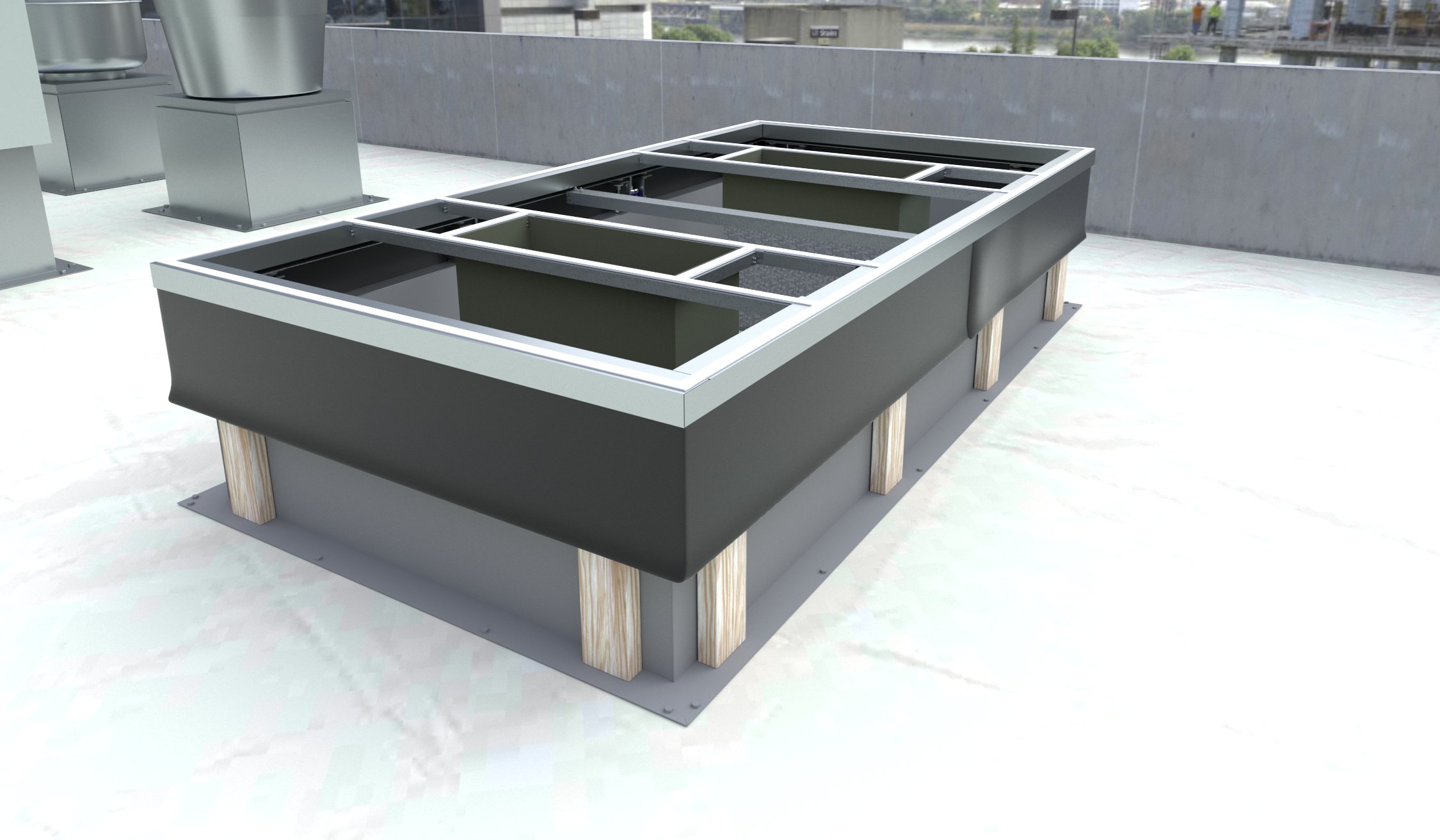
The support of piping and conduit in the interstitial space is often achieved with hangers suspended from the raised deck, or brackets attached to the stem walls or bearing on the structural deck. Depending on the configuration of the waterproofing membrane in the interstitial space (e.g. continuous on structural deck versus up and over stem walls), the various methods to support utilities each carry performance risks, and they should be evaluated in that light. Where possible, it is best to avoid penetrating the waterproofing with utility supports altogether. At a minimum, it is best to provide several inches of clearance below and adjacent to horizontal utility lines to permit future waterproofing repairs (Figure 5), support the utility hangers with round stanchions with flush post-installed anchor heads to facilitate flashing, and always avoid attaching brackets with irregular section profiles directly through the waterproofing (Figure 6), as the fastener penetrations are blind and unable to be reliably made watertight. Additionally, wherever piping or conduit must penetrate the waterproofing, it must do so a minimum of 102 mm (4 in.) away from walls and curbs to permit proper flashing installation. Finally, to the extent permitted by plumbing and electrical regulations, it is advisable to avoid the use of flexible corrugated piping/conduit at the penetration locations, since waterproofing materials cannot predictably fill the corrugations and eliminate the numerous pinholes that are inherent to the corrugated shape during the flashing operation.
Sign up for our weekly newsletter
Architectural materials and methods delivered right to your inbox
- CSI News and Notes: CSI Foundation’s construction camp; CSI spring exam; and more
- CSI News and Notes: CSI’s credentials; CSI conference theme; and more
- To be specific – CSI supports young AECO professionals
- CSI News and Notes: CSI’s foundation scholarships, national conference, and Crosswalk
- CSI News and Notes: AI’s impact; CSI 2024 conference, and more
Related Products
Read the Latest Issue

