Amenity roof design challenges: Coordinating waterproofing and drainage with luxury features
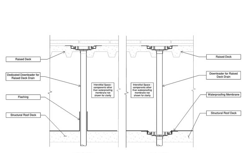
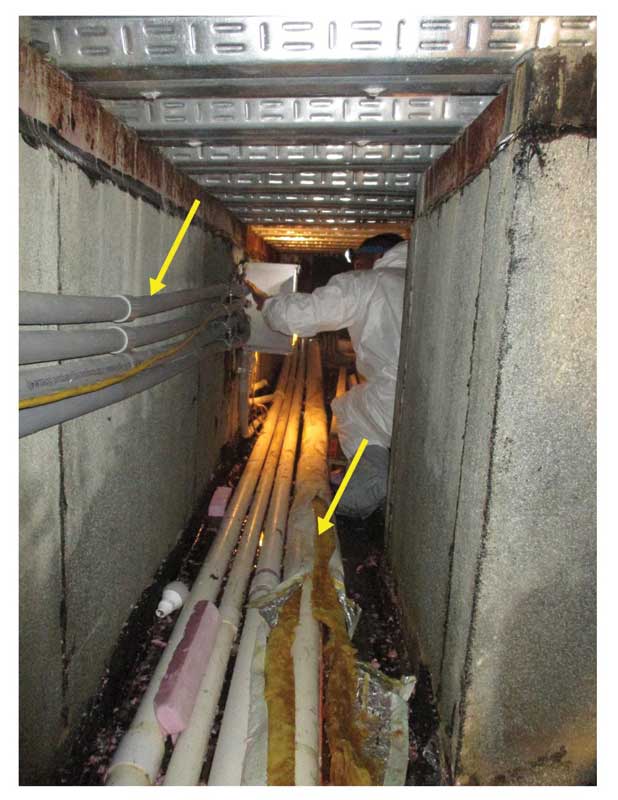
A future maintenance plan for interstitial space utilities, the waterproofing membrane, and drains should also be considered during the design phase and communicated with the building owner, since these items will require maintenance, repairs, and eventually replacement when in service. Some panelized raised deck systems (e.g. wood decking if permitted by local code) inherently permit future access by virtue of their removable planks, while other monolithic upper-deck systems (e.g. cast-in-place concrete on metal form deck) warrant more careful consideration of the quantity, size, and location of access hatches that should be included in the design. Provisions for natural ventilation (if the space above the waterproofed structural deck is unconditioned) through the interstitial space are also prudent to include in the design from the standpoint of minimizing moisture buildup and minimizing the potential need for safety engineering controls, such as forced-air ventilation during maintenance activities. Ultimately, developing a design for an interstitial space that does not later surprise the owner by necessitating a costly permit-required confined space program to perform routine maintenance below the raised amenity deck should be the goal.
Rooftop landscaping and guardrails
Incorporating landscaping in the design of rooftops is a process that, in recent years, has benefitted from increased understanding of vegetative roofing in the architecture, engineering, and construction (AEC) fields. The lack of coordination between waterproofing details and drainage with landscaping features, however, continues to haunt some project teams with many unintended problems.
One example of a risk-avoidance design opportunity relates to the specification and design detailing of a popular amenity feature—steel-walled planters. These products—comprising of vertical steel wall plates, horizontal steel base plates, and steel gusset-plate stiffening elements—require fastening into a structural substrate through the base plates. If the waterproofing membrane is located on the structural deck and the base plates are designed to bear directly on the deck, the post-applied bolt anchors securing the base plates create blind penetrations through the waterproofing that cannot be reliably sealed by simply applying excess fluid-applied waterproofing material or sealants over the bolts. Alternatively, specifying a concrete curb, either with regularly spaced discontinuities or with intentionally located block-outs (similar to the interstitial drainage/stem wall drainage discussion earlier) with continuous waterproofing below the curb is the preferred practice, as it decouples the planter bolt penetrations from the waterproofing.
Glass guardrails, commonly specified on amenity roofs, present similar risks and coordination opportunities as the steel-walled planter. Whereas traditional steel-pipe-stock guardrails can be specified with round stanchions to facilitate the detailing and reliable base flashing detailing, glass guardrails, particularly those with the desirable continuous/frameless appearance, require a continuous aluminum ‘shoe’ to capture the glass lite. Most stock glass guardrail shoes are designed to be anchored through the bottom into the substrate. Like the steel planter base plate fasteners, aluminum shoe fasteners should not penetrate the waterproofing in a blind configuration and rely on sealant. It is advisable to employ the concrete curb approach described earlier.
Traditional rooftop landscaping elements such as concrete-walled planters can also be at risk of missed coordination opportunities. The authors visited a project site where the intended drainage features at such a planter were rendered inoperable due to lack of coordination. The architectural drawings and specifications appropriately and consistently showed rooftop concrete planters lined with, from interior to exterior, a hot-rubberized asphalt waterproofing membrane, root barrier, and drainage composite. The plumbing specifications appropriately indicated a bi-level planter drain product with openings at the waterproofing membrane level. However, the planters were filled with several inches of a concrete overlay, blocking both the waterproofing-level drain opening and the vertical drainage composite installed at the bottom of the planter wall. Rainwater collecting in the planter would have only one outlet—after ponding to a depth of several inches, it would eventually reach the upper openings in the vertical standpipe of the drain, but only after creating unnecessary water leakage risk and other unintended consequences, such as compromising the health of the plantings and attracting mosquitoes. In this instance, the landscape designer—with prudent intentions—had specified the sloped concrete overlay to improve planter drainage, but the concrete overlay was never represented (or therefore reviewed) in a coordinated design detail that included the waterproofing, drainage composite, and application-specific drain.
Ramps
For pedestrian comfort or the provision of Americans with Disabilities Act (ADA), rooftop amenity spaces commonly require ramps linking varying wearing surface elevations. A common design strategy for ramps on an amenity roof is for the ramp wearing surface to be cast-in-place concrete, where the concrete is placed on a sloped stay-in-place geofoam form. The perimeter of the ramp will include downturned curbs bearing on the waterproofed structural deck. Since rapid and unobstructed drainage of the waterproofing membrane reduces leakage risk and prolongs the life of the membrane, the presence of the geofoam warrants the specification of a drainage composite layer to be included between the waterproofing membrane and geofoam fill. Additionally, the footprint of the ramp must be considered as a ‘zone’ of the amenity roof interstitial space, and the drainage recommendations outlined above should be implemented in coordination with the structural and plumbing engineers.
Sign up for our weekly newsletter
Architectural materials and methods delivered right to your inbox
- CSI News and Notes: CSI Foundation’s construction camp; CSI spring exam; and more
- CSI News and Notes: CSI’s credentials; CSI conference theme; and more
- To be specific – CSI supports young AECO professionals
- CSI News and Notes: CSI’s foundation scholarships, national conference, and Crosswalk
- CSI News and Notes: AI’s impact; CSI 2024 conference, and more
Related Products
Read the Latest Issue