Assessing mass concrete with thermal control plans
by arslan_ahmed | October 20, 2023 8:08 pm
 [1]
[1]By Eric Van Dixhorn
As schedules on construction projects continually accelerate and service life requirements become more demanding, structures are being built larger and to last longer. As a result, more attention has been placed on the internal heat generation that takes place while the concrete cures. If ignored, this heat can lead to thermal cracking and reduced long-term strength. Concrete elements that require a thermal analysis are labeled as “mass concrete.”
Traditionally, mass concrete is widely used in dam structures, bridge piers, mat foundations, and other large structures that require substantial volumes of concrete. Thermally controlled concrete (referred to here as mass concrete) may not have the same volume and dimensional characteristics as traditional mass concrete, but it requires thermal considerations because the higher cementitious content leads to higher internal temperatures.
There is no universal definition of mass concrete. In many cases, if the element’s smallest dimension is greater than 1.2 m (4 ft), then it should be categorized as mass concrete. According to the American Concrete Institute (ACI), mass concrete is “any volume of structural concrete in which a combination of dimensions of the member being cast, the boundary conditions, the characteristics of the concrete mixture, and the ambient conditions can lead to undesirable thermal stresses, cracking, deleterious chemical reactions, or reduction in the long-term strength as a result of elevated concrete temperature due to heat from hydration.” If precautions are not implemented on a mass concrete pour, these undesirable results can have substantial financial consequences.
ACI 301, Specifications for Structural Concrete, states the maximum temperature after placement should not exceed 71 C (160 F), and the maximum temperature difference between the core and the surface should not exceed 19.4 C (35 F)—which is differential and not absolute temperature. In the absence of a more thorough analysis, these are generally considered to be safe and cautious specifications. Thankfully, ACI provides a guide (ACI 207) that allows specifiers and engineers to deviate from these requirements through the development of a thermal control plan (TCP).
 [2]
[2]Thermal control plan
A TCP is a document typically prepared by an experienced licensed engineer who is knowledgeable on the thermal behavior of concrete. A TCP provides a foundation to ensure high thermal stresses and cracking of mass concrete will be avoided, and that its long-term durability will not be negatively affected. This is attained through the control of both the maximum temperature in the concrete (at the core or center of mass) and the temperature differential between the core and the outside faces of the concrete elements. It is an action plan for the contractor that includes information on mix design optimization, concrete cooling options, allowed concrete temperatures at point of placement, expected temperature rise, requirements for form insulation, anticipated duration of the thermal control period, requirements of number and location of the concrete temperature sensors, and more.
Historically, most specifications and TCPs follow ACI 301 with respect to the temperature restrictions. In many cases, a thorough analysis of the design and the corresponding mix constituents allows the engineer to offer less restrictive requirements, especially when it comes to the temperature differential.
The purpose of limiting the temperature differential within the element is to avoid thermal cracking that can result from a large temperature difference between the center and exterior surfaces. Temperature differentials lead to internal stresses, and if the concrete (especially in the first few days of curing) is not able to resist the temperature-induced stresses, cracking will result. The cracking can result in long-term structural and durability issues.
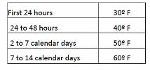
ACI’s limit of 19.4 C (35 F) is safe, conservative, and simple to implement, which is why this limit has typically been the standard for most projects. However, the main shortcoming of this restriction is that it does not account for the strength the concrete gains while it cures. Having recognized this shortcoming, numerous agencies and institutions have implemented a temperature differential approach that is based on time. This method is typically referred to as a stepped temperature differential limit.
 [3]
[3]Although the stepped approach is an improvement compared to the set limit, the specifications are making assumptions on the concrete’s strength as it cures. Thankfully, there is another method: the performance-based temperature differential limit (PBTDL).
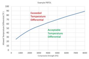
Performance-based temperature differential limit
The PBTDL method provides a temperature differential limit that is directly tied to the concrete’s compressive strength. It completely replaces the 19.4 C (35 F) temperature differential limit. Essentially, the allowed temperature differential will increase as the concrete gains strength. Initial testing on the mix is required to determine material properties, such as elastic modulus, tensile strength, and the coefficient of thermal expansion. These properties are used to develop a chart that provides the temperature differences the concrete can resist without resulting in thermal cracking.
The strength of in-place concrete is determined through the maturity method, which is an ASTM standard that correlates the temperature history to strength. This means, if the temperature of the concrete is being tracked while it is curing, the maturity method can accurately determine the real time in-place strength.
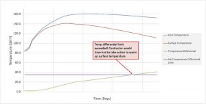
The development of a performance-based TCP may require additional pre-planning compared to a traditional plan. However, the cost savings in the field far outweigh any of the additional engineering costs. Figure 2 shows an example of a typical concrete temperature curve. For both the core and the surface, the temperatures typically climb and peak around the first two days, with the core temperature exceeding the surface temperature. The differential between the two will start to rapidly increase as the surface temperature starts to cool significantly faster than the core. It is common to see the temperature differential peak around the third or fourth day.
 [4]
[4]Assume the contractor is using a TCP with a set 19.4 C (35 F) temperature differential. To avoid breaching the threshold, the contractor would potentially need to add blankets/insulation to the exterior surface to minimize the heat loss. In other cases, the contractor may even be required to heat the surface using propane or diesel heaters. In either case, there are significant costs to these operations—potentially thousands of dollars per pour (Figure 2).
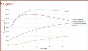
Consider the same scenario, but assume the contractor is using a PBTDL. In this situation, the concrete gains strength, and the allowed temperature differential also increases and stays safely above the actual measured differential. This avoids the headaches, costs, and environmental impact with heating the surface of the element (Figure 3).
 [5]
[5]Conclusion
The set temperature differential method can be easier to understand and simpler to implement. However, as awareness increases with the limitations of the traditional set temperature differential, coupled with the technology improvements for the concrete sensors, the use of a PBTDL approach is rapidly gaining popularity. Contractors can access the temperature data remotely and in real time. This means they do not need to be on-site to see their temperature or strength data. They can access the data remotely, providing critical information on concrete temperatures, temperature differentials, strength, and allowed temperature differential. This advantage allows contractors to be more proactive from both a quality control (QC) and operational standpoint.
A PBTDL approach can require more upfront engineering, but for proactive contractors that have mass concrete projects, the operational and time savings can be impactful. Contractors, engineers, and building owners who embrace the benefits of using PBTDL will reap the rewards now and in years to come.
 Author
Eric Van Dixhorn serves as technical sales director at Brickeye, a leader in advanced IoT solutions for construction and industrial applications. Based in Colorado, he holds a bachelor’s degree in civil engineering and has a background in construction, with a specialty in heavy-highway and infrastructure construction. Previously serving as vice-president of engineering at NITROcrete, Dixhorn has more than a decade of experience in the industry.
- [Image]: https://www.constructionspecifier.com/wp-content/uploads/2023/10/Construction-Canada_Image-1.jpg
- [Image]: https://www.constructionspecifier.com/wp-content/uploads/2023/10/Figure-1-1.jpg
- [Image]: https://www.constructionspecifier.com/wp-content/uploads/2023/10/Figure-3.jpg
- [Image]: https://www.constructionspecifier.com/wp-content/uploads/2023/10/figure3-mass-concrete.jpg
- [Image]: https://www.constructionspecifier.com/wp-content/uploads/2023/10/Figure-2-2.jpg
Source URL: https://www.constructionspecifier.com/assessing-mass-concrete-with-thermal-control-plans/