Avoiding Problems in Aquatics Facilities: Atypical design for atypical buildings
by Molly Doyle | December 25, 2013 10:04 am
 [1]
[1]by Jason S. Der Ananian, PE, and Sean M. O’Brien, PE, LEED AP
If an office building in a cold climate is designed to run at a slight positive pressure while omitting air barrier details at the building enclosure, the likely consequences include higher energy costs and potentially isolated condensation events or freezing pipes during very cold weather, with problems developing in five to 10 years. If this was a natatorium, however, the resulting damage may include human-sized icicles at roof eaves, concealed corrosion of metal framing components, widespread efflorescence on exterior concrete and masonry, and premature failure of the building enclosure components—often within months.
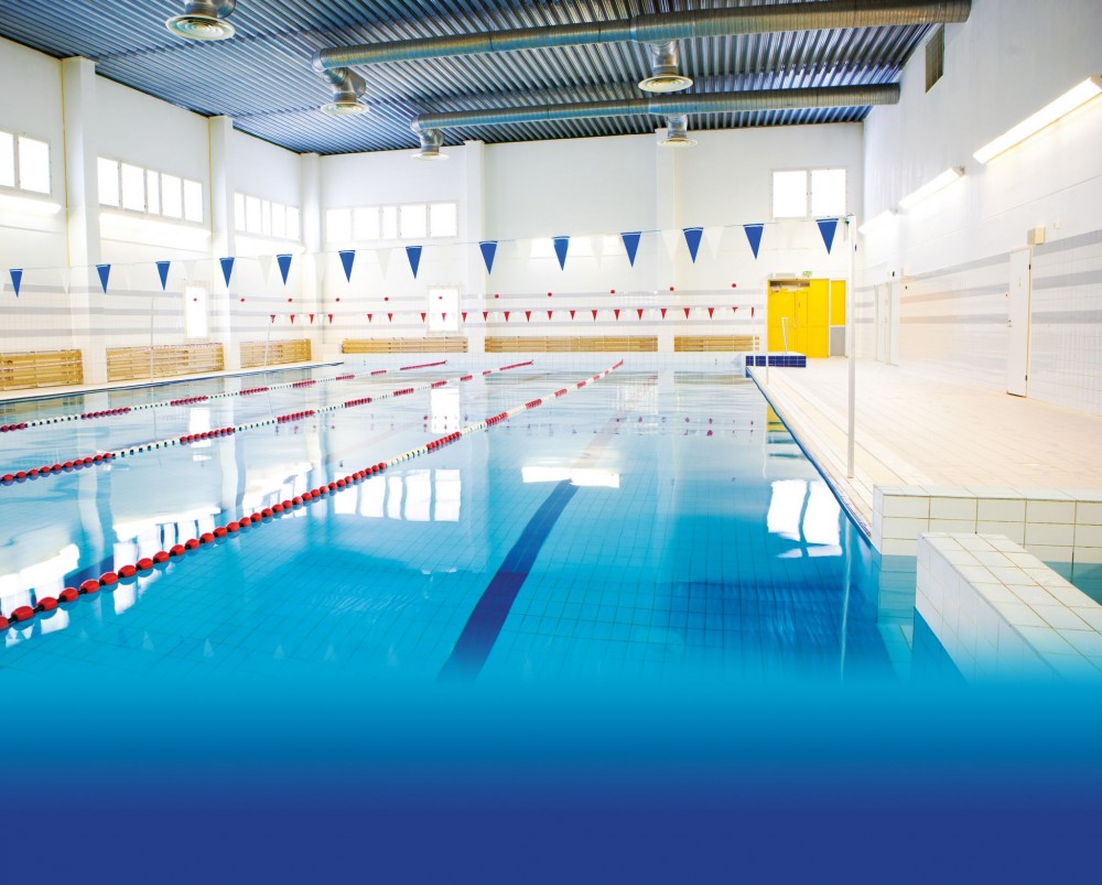
Few, if any, building types present the risks and challenges found in indoor swimming pool facilities. With far higher interior moisture loads than typical buildings and a potentially corrosive interior environment, natatoriums put structural and enclosure systems to the test, especially in cold or even mixed climates.
The authors’ firm has investigated dozens of natatoriums throughout the country and witnessed firsthand the swift and severe nature of failures that can result from improper design and construction. In some cases, the design included the primary components necessary for moisture control, but lacked transition details or did not adequately define the system’s continuity. Others were well-designed but poorly constructed, or poorly designed but built exactly as shown on the drawings. Still others may have functioned well from an enclosure standpoint, if not for significant shortcomings in the mechanical systems’ design or operation.
 [2]
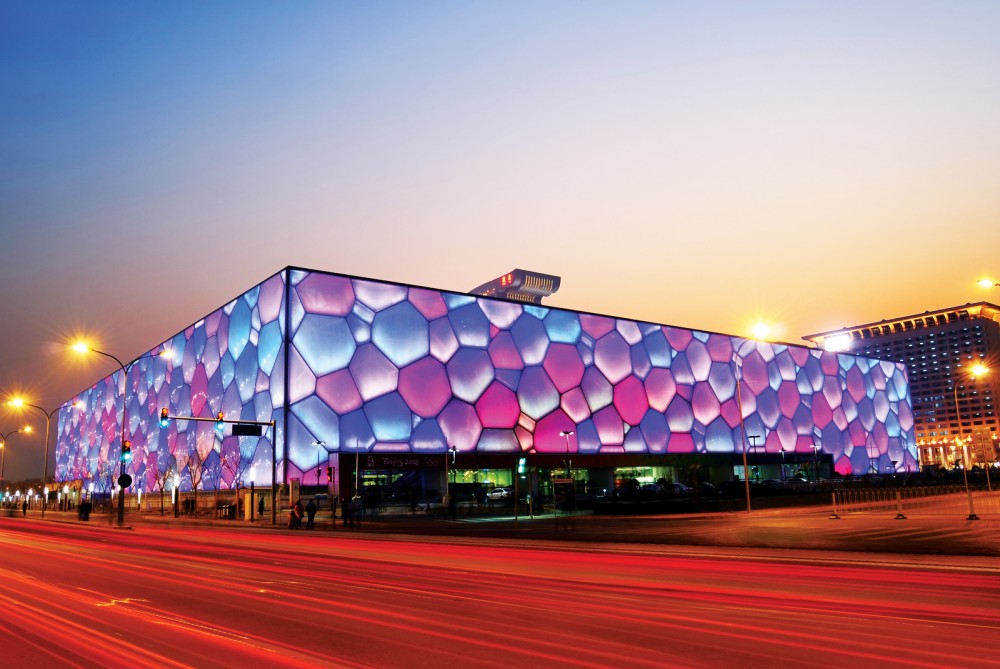
[2]Problems are often found in natatoriums that are part of a larger athletic complex where designers fail to make the distinction between ‘typical’ enclosure systems and more specialized systems required for pools, or fail to prevent moisture migration between the pool and adjacent spaces.
Moisture loads and controls in natatoriums
The air in a natatorium often contains nearly three times the moisture per unit volume as a typical, non-humidified building. This greatly increases the importance of controlling moisture transport through the building enclosure. Typically, three forms of moisture transportation can contribute to problems:
- water leakage;
- water vapor diffusion; and
- airflow.
Water leakage, which occurs when water finds a path into the building, is controlled through water management and waterproofing systems that are beyond this article’s scope. Water vapor diffusion, or the movement of water vapor driven by vapor pressure differentials, is typically a slow process that can result in long-term moisture accumulation or condensation within the building enclosure cavities; it is controlled by a vapor retarder.
Airflow is the main contributor to water vapor and heat transport in the enclosures of most buildings. Unless it is controlled by an effective air barrier system, air will flow through the building enclosure cavities where it can condense on cooler surfaces as it travels toward the exterior.
Although critical for moisture control in natatoriums, non-humidified buildings can often provide moderate (although not necessarily optimal) performance and avoid condensation without air barriers in the enclosure, and vapor retarders may only be necessary in extremely cold climates. This is reflected in most building codes, which, until recently, made no mention of continuous air barriers and often do not require vapor barriers in warm or moderate climates (Climate Zones 1 through 4, as defined in American Society of Heating, Refrigerating, and Air-conditioning Engineers (ASHRAE) 90.1, Energy Standard for Buildings Except Low-rise Residential Buildings.
However, it is important to realize the building code is intended for non-humidified/‘general-use’ buildings, and does not specifically cover special buildings such as natatoriums and museums—both of which require atypical interior conditions. The authors’ firm has investigated many natatoriums that complied with building enclosure requirements outlined in the applicable building code, yet still suffered from significant moisture problems. Relying solely on the building code for design guidance is unlikely to result in a durable, functional natatorium.
 [3]
[3]
Air and vapor flow through natatorium enclosures
High moisture levels in natatorium environments greatly increase the risk of interior surface condensation on cold components, such as windows, doors, roof penetrations, and drains. These conditions also provide an ideal environment for condensation to collect within walls and roofs due to air leakage and vapor diffusion.
Humid air from natatorium spaces that migrates into the exterior walls condense once reaching a surface below the air’s dewpoint temperature. Condensation concealed within wall or roof assemblies may go unnoticed by the building owner until these assemblies are severely degraded. For a natatorium in cold climates, the risk of condensation exists for most of the year, often eight to 10 months. Moisture levels can be significantly reduced by covering the pool when swimmers are not present, but problems may still occur when the natatorium is actively being used.
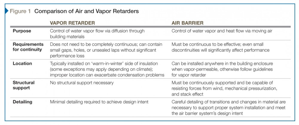
A properly designed natatorium building should include both a vapor retarder and, more importantly, a continuous air barrier system in the walls and roofs to minimize moisture migration through the enclosure (they may or may not be formed from the same material). Although the terms ‘vapor barrier’ and ‘air barrier’ are often used interchangeably, the two systems have differences in the way they control moisture and the construction necessary for them to be effective. Figure 1 highlights these differences.
Controlling air and vapor flow
Vapor retarders minimize water vapor’s flow through materials by diffusion. Water vapor can flow through the internal pore structure of apparently solid materials such as wood, concrete, and gypsum board. If the air within a building has higher moisture content than the exterior environment, the vapor drive is toward the exterior, tending to ‘push’ water vapor from the inside to the outside.
In cold and mixed climates, this water vapor may condense within the wall or roof as the temperature drops. In this case, a vapor retarder on the interior—or ‘warm’—side of the insulation helps prevent water vapor from reaching colder temperatures, minimizing the risk of condensation in the wall. Conversely, a vapor retarder on the wrong side of the wall, outboard of the primary insulation where it experiences low temperatures, can act as a collection point for condensation and lead to more significant problems than if no vapor retarder was installed. Since the driving force behind water vapor diffusion is relatively minimal, vapor barriers can contain small holes, such as fastener penetrations, and do not require sealed laps to be effective. Even if larger discontinuities exist, damage due to moisture migration in these areas will tend to be localized.
 [4]
[4]Moving air carries both heat and moisture. The magnitude of moisture migration via airflow can be 50 to 100 times that associated with water vapor diffusion alone. Air flows from high to low pressure regions. In buildings, such differentials can result from mechanical system operation, wind, stack effect, or a combination thereof. These pressure differences can exert significant force on air barrier systems, making it necessary for air barriers to have continuous structural support. Even small holes or discontinuities in the air barrier can allow significant air leakage and greatly reduce the system’s effectiveness, especially in buildings with high moisture levels. Complicating matters, a small hole on the interior can lead to air leakage into many other locations, as opposed to creating localized damage as with discontinuous vapor retarders.
The air barrier in a building is more than just a single material. It comprises interconnected components including airtight materials in walls, roofs, doors, windows, curtain walls, and other enclosure elements. To maintain the system’s continuity, airtight transitions are needed between all components, including interior partitions separating the natatorium from adjacent spaces.
The goal of a well-designed and properly installed air barrier is to eliminate uncontrolled airflow through the building enclosure. Uncontrolled airflow results in increased heating and cooling loads; it can also transport moisture or chlorinated air to areas where moisture or odor exposure is undesirable. Critical transitions, such as the roof-to-wall intersection, must be carefully detailed, as poor transitions can greatly reduce air barrier performance and mechanical system effectiveness in controlling building pressure.
The air barrier’s construction is just as important as its design. Success requires coordination between multiple trades at multiple points in the schedule, such as roof-to-wall intersections and window/curtain wall perimeters. Designers must take into account the potential for sequencing conflicts during construction.
Interior partitions that separate interior high-humidity zones from adjacent, non-humidified or even unconditioned interior zones are an oft-overlooked component of the natatorium air barrier system. Natatoriums are commonly part of a larger complex of buildings. Since spaces like offices, storage rooms, and gymnasiums are not usually designed to function under high-humidity conditions, moisture-laden airflow into those spaces through unsealed interior partition walls may lead to significant damage to interior components. Additionally, leakage into adjacent spaces may cause damage to exterior components, if those spaces are located near exterior walls not designed to tolerate high humidity.
Even in the absence of condensation, airflow to and from adjacent spaces can also minimize the mechanical system’s ability to control air pressure within the natatorium (discussed in more detail later in this article). Unless a space is specifically designed to tolerate high humidity, it must be completely air-sealed and isolated from any adjacent spaces that may function as moisture sources.
Natatorium investigation reports reviewed by the authors’ firm almost always cite “improper design/construction of the vapor retarder” as a primary cause of moisture problems. However, in natatoriums, even the absence of a vapor retarder rarely produces the same level of damage as an improperly designed/built air barrier system. This common confusion between air barriers and vapor retarders often results in poorly designed natatoriums and short-term failure of building enclosures.
Controlling interior surface condensation
Interior moisture levels in natatoriums are high, with dewpoint temperatures ranging between 12.8 and 18.3 C (55 and 65 F). Natatoriums in cold (and even mild) climates are susceptible to condensation on interior surfaces that drop below the ambient dewpoint during the winter. As such, interior surfaces in natatoriums must be kept warm, often as high as 18.3 C, to prevent condensation.
 [5]
[5]Opaque walls and roofs can typically be designed with continuous insulation and high R-values to meet this criterion. Windows, doors, and curtain walls must be high-performance thermally broken systems designed for high-humidity applications, although even the best fenestration likely experiences surface condensation or frost during the coldest times of the year.
Surface condensation can degrade adjacent construction materials and cause ‘fogging’ on glass surfaces. Several design strategies are effective at reducing the risk of interior surface condensation, including:
- using high-performance fenestration systems;
- aligning fenestration systems with the insulation;
- avoiding installing highly conductive materials against fenestration; and
- providing air curtains or directed flows of warm air over components or using electric heat-trace cables to deliver supplemental heat directly to glazing and framing systems (often the only way to completely eliminate condensation in cold-climate natatoriums).
Unlike ‘passive’ condensation control systems, such as thermally broken window frames, mechanical and electrical systems require regular maintenance to remain operational.
Natatoriums often include skylights to provide occupants with natural light. The increased condensation risk at skylights is due in part to their orientation; mounted in low-slope roofs or near-horizontal applications, skylights tend to lose more heat through radiation to the sky compared to similarly sized windows and doors (especially at night).
Supplemental heating systems can be difficult to install due to the high visibility of skylight systems. A compromise would be to design a high-performance skylight and install a system of gutters around the perimeter, ensuring any condensation is collected and drained (rather than dropping from the ceiling onto occupants). For gutters to be effective, skylights should be fairly steep in slope so condensing moisture flows down the glass surface to the sill gutters, rather than dripping into the space as can occur in low-slope skylights. The maintenance and cleaning of active condensation control or weep systems can be difficult, particularly on skylights located directly above the pool(s).
 [6]
[6]Natatorium air pressure control
It is impractical to achieve a perfectly airtight enclosure, and even small amounts of air leakage can result in condensation. Therefore, natatoriums must be maintained at a negative pressure relative to adjacent interior spaces and the exterior to minimize odor migration and potential for airflow-induced condensation in building enclosure cavities during winter. The 2011 ASHRAE Handbook–HVAC Applications recommends maintaining a negative pressure of between 12 and 37 Pa (0.25 and 0.77 psf) in the natatorium to minimize moisture and odor migration.
Interior partition wall openings, including doors, require gaskets to allow the HVAC to more efficiently control building pressures. Maintaining a negative pressure in the natatorium commonly involves balancing the mechanical system to return more air than is supplied into the building while maintaining the minimum required outdoor airflow rate per ASHRAE Standard 62.1-2010, Ventilation for Acceptable Indoor Air Quality.
It is important to understand simply providing more exhaust air than outside air is not sufficient to maintain negative pressure. Even with no outside air and significant exhaust flow, if the quantity of air supplied to the natatorium exceeds the amount returned (due to improperly sized or restricted ductwork, the operation of mechanical systems in adjacent spaces, etc.) the natatorium pressure will still be positive.
The HVAC system’s ability to control building pressure relies heavily on the airtightness of the natatorium enclosure. Controlling building pressures in a ‘leaky’ natatorium is difficult compared to a relatively airtight one. For these reasons, testing and balancing of the natatorium HVAC system should occur following the air barrier system’s completion.
Depending on the climate zone in which the natatorium is located, supplemental exhaust fans may also be necessary to maintain pressure control during the coldest times of year, particularly for facilities with high ceilings or in retrofit applications where the existing mechanical system cannot be practically or appropriately modified.
In cold climates, even with a properly balanced natatorium mechanical system, positive pressure may occur near the ceiling due to stack pressure (i.e. buoyancy of air). The authors often find natatoriums running ‘under negative pressure,’ where the slight differential at the pool deck level is insufficient to overcome stack pressure, allowing for high pressures and significant air exfiltration at the roof level where critical details such as roof-wall intersections often occur.
The supplemental exhaust fan (or even the primary mechanical system fan[s]) is best controlled by a pressure sensor located near the pool ceiling that time-averages the pressure differential between the interior and exterior; a control system speeds up or slows down the exhaust fan accordingly to maintain a zero pressure difference between inside and out. Similarly, pressure should be measured near the high point of the natatorium during testing and balancing of the mechanical systems—preferably during cold weather—to obtain a more accurate measure of pressure within the space.
Construction mockups of air barrier systems
Construction mockups are typically required for projects to verify both aesthetic and technical aspects of the design. As part of this project phase, mockups of the air barrier should include typical transitions (e.g. wall-to-fenestration, wall-to-roof, etc.) for review by the architect or third-party inspector. This work shall be used to:
- test installation methods;
- determine construction defects (if any);
- establish the technical and aesthetic standard of care for the project; and
- refine, if necessary, installation methods in accordance with the design intent before construction proceeds.
Mockups are also helpful for coordinating between trades.
The mockups should be performed as many times as necessary for approval by the architect and/or third-party inspector. Inspection of the air barrier should not be pushed to the punch list phase—testing of air barrier mockups should be performed before cladding installation to ease identifying and repairing of breaches.
Field testing of air barrier continuity
Performing whole building air infiltration testing can help verify the performance of air barrier installations as well as locate system defects in new and existing buildings. Several agencies and state building codes even require whole building air infiltration testing for new buildings. It is prudent to perform testing before the air barrier system is concealed by cladding materials or interior finishes so defects can be identified and repaired more easily. Removing cladding after construction is complete to locate air barrier discontinuities is often costly and disruptive to building occupants.
 [7]
[7]Field testing requires the building be positively or negatively pressurized using blower door fans or manipulating the HVAC system to force air to leak through any air barrier discontinuities in the building enclosure. Various quantitative and qualitative techniques are available to identify leakage paths, including tracer smoke and infrared (IR) thermography. The architect should write the field testing requirements of air barriers into the project specifications.
Qualitative air leakage testing
ASTM E1186, Standard Practices for Air Leakage Site Detection in Building Envelopes and Air Barrier Systems, describes various qualitative methods to locate air barrier discontinuities. One such practice is to pressurize or depressurize the building or individual spaces by using fans or by manipulating the HVAC system, and then using a tracer smoke source over the interior or exterior surfaces of the building enclosure.
Placing the tracer smoke source at the building interior and pressurizing the building or space to locate air exfiltration sites reduces the influence of wind or stack effect. In this case, tracer smoke will be ‘pushed’ from the building through any breaches in the air barrier and be identifiable at the building exterior (Figure 2).
Although it is possible for some projects to depressurize the building and locate the source of tracer smoke on the exterior, this method may be difficult because of the influence of wind and the risk tracer smoke rapidly dissipates before it is drawn into the interior through the air leakage site.
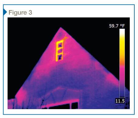
IR thermography (per ASTM E1186) is another useful and efficient qualitative method to locate discontinuities in the air barrier. The purpose of the IR scans is to identify locations of elevated heat loss through the building enclosure. Air infiltration or exfiltration through the building enclosure affects the temperature of wall or roof components in the region of air leakage pathways, given the interior and exterior temperature difference; IR scanning equipment can be used to detect local surface temperature differences (Figure 3).
The conditions most conducive to accurate IR scans are low winds with a large temperature difference (at least 16 C [30 F]) between the interior and exterior air temperatures. Using fans or the HVAC system to pressurize or depressurize the building during the IR scans can exacerbate air leakage through discontinuities in the air barrier, making it easier to identify air barrier breaches on an IR image. Since thermal bridges or insulation discontinuities in the enclosure can also result in surface temperature differentials, it is typically necessary to perform multiple scans—from both the interior and exterior, and with the building under positive and negative pressure—to isolate the contribution of thermal bridges and more accurately identify air leakage sites.
Quantitative air leakage testing
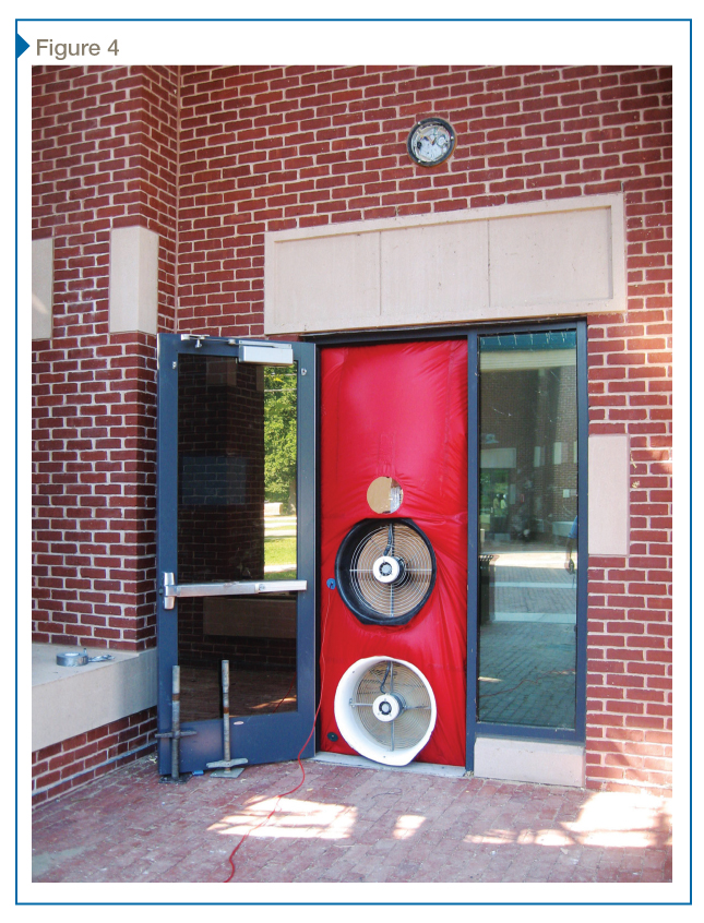
Blower door testing per ASTM E779, Standard Test Method for Determining Air Leakage Rate by Fan Pressurization, is intended to characterize the airtightness of the building enclosure. The test results can be used to compare the subject’s airtightness to similar buildings or against criteria set by industry standards and governing building codes; it can also be used to determine how readily the HVAC system can be adjusted to control pressure and reduce leakage. The tests are conducted using calibrated fans (Figure 4) to pressurize or depressurize the building under controlled conditions.
The ASTM E779 test procedure typically requires a range of induced pressure difference (pressurization and depressurization) from 10 to 60 Pa (0.2 to 1.25 psf). The measured air leakage flow rates (cubic feet per minute) are typically normalized using the above-grade building surface area (walls and roof) and calculated as an air leakage rate at 75 Pa (0.3 in. water column) pressure difference.
While quantitative testing is useful from an overall performance standpoint, a qualitative leak assessment should always be done in natatoriums due to the potential for condensation problems even at small leakage sites. On the same note, when the building is extremely airtight, but experiences all the leakage at one large air barrier breach in the enclosure, identifying the location of that breach is critical.
 [8]
[8]Corrosion issues
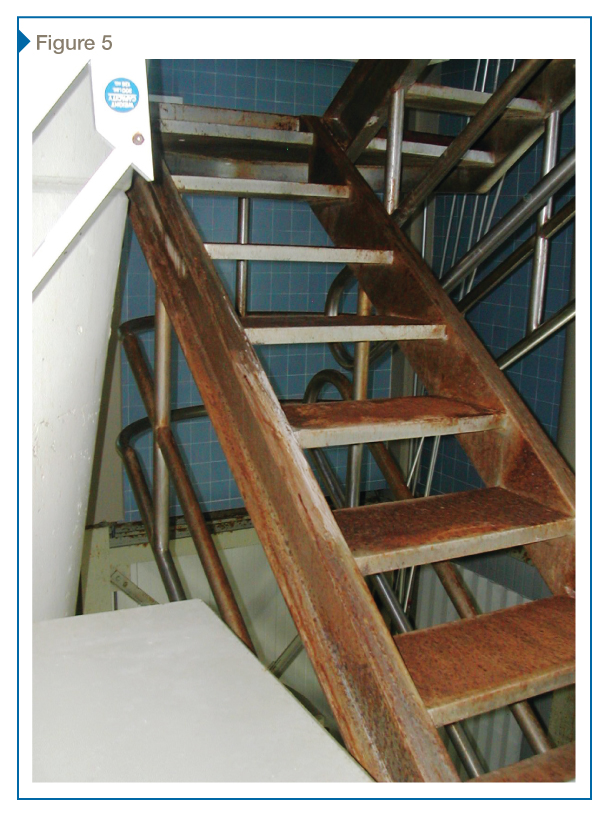
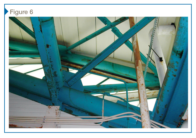
Although some pools have begun to employ alternative technologies to treat pool water, such as ozone or ultraviolet sterilization, the majority of swimming pools still use chlorine-based chemicals for pool water treatment. This is primarily due to the higher initial cost of alternative treatment systems, but also the entrenched nature of chlorination as a means of water treatment, which has been in use for more than a century. While an effective disinfectant, chlorine has the unfortunate side effect of being highly corrosive to typical steels and even some stainless steel alloys.
The most common form of corrosion in natatoriums is visible surface corrosion, which affects bare steel or steel with insufficient corrosion protection. This can affect both materials which are directly exposed to pool water (Figure 5) and those which have no direct wetting and are affected by the chlorine compounds in the air only (Figure 6). In both cases, corrosion can be greatly exacerbated by improper maintenance of the pool water chemistry, which can result in higher levels of chlorine compounds in both the water and air.
Stainless steels are often used in swimming pools to combat corrosion, but even these specialty metals have their limitations—especially in chlorinated environments. Common alloys such as Types 304 and 316 can work well in areas where the components are frequently cleaned or wetted/splashed, as this tends to prevent chloride compound buildup on surfaces.
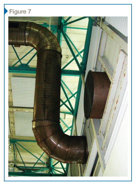
Infrequently cleaned surfaces may corrode quickly once a film of chlorides builds up on their surfaces (Figure 7). This is counterintuitive to many designers, since a stainless steel component that never comes into contact with pool water would, at first glance, appear to have little risk of corrosion. Stainless steel ductwork (often specified due to its perceived superior corrosion resistance) is one of the most commonly corroded items, but stainless steel light fixtures or hangers are also at risk.
Some stainless steel components are also susceptible to the more dangerous stress corrosion cracking (SCC). This type of corrosion often produces little to no outward evidence; rather, it affects the steel’s structure, leading to sudden, brittle failure. For SCC to occur, a susceptible grade of stainless steel (most standard chromium-nickel stainless steels, such as Types 304 and 316, fall into this category) must be placed in a corrosive environment and subjected to a tensile load. Hanger rods for overhead components are the most commonly affected, although other formed metal components, which can contain residual tensile stresses from forming operations, can also fail due to SCC.
There have been several examples of structural failures due to SCC in natatoriums, including ceiling collapses in:
 [9]
[9]- Switzerland (1985), due to failure of stainless steel hangers (resulting in 12 reported casualties);
- Netherlands (2001), due to failure of stainless fasteners; and
- Finland (2003), due to failed stainless steel hangers.
This risk means using stainless steel in overhead or safety-critical components must be carefully evaluated. In these cases, specialty alloys such as those containing higher levels of nickel and molybdenum (e.g. Types 904L and 254 SMO), which are more resistant to SCC, are likely necessary.1[10]
Although stainless steels tend to be more expensive than painted steel or aluminum, the higher initial cost is typically justified by reduced long-term costs associated with maintenance, repair, or replacement. This is especially true for components at or near the pool deck which are routinely wetted. Most other metals, even those painted or galvanized, will have greatly reduced service lives in these applications.
For larger structural applications, stainless steel is not practical in terms of cost and availability. In these applications, high-performance paints/coatings—often combined with galvanization—are required for long-term performance. As shown in Figure 7, breakdown of applied paints can result in rapid corrosion of the base metal. Even with high-performance coatings, owners should expect some maintenance and eventual recoating of steel components.
Summary of design strategies
Based on the discussion in this article and personal experience in the design, construction, and investigation of natatoriums, the authors present the following summary of design guidelines for indoor swimming pools. (This is not an exhaustive list of all design concerns, but focuses on primary issues with the building enclosure and interior environment.)
- Design a continuous air barrier system for the exterior enclosure, including exterior and interior components that separate the natatorium from adjacent spaces.
- Design continuous insulation for the enclosure and minimize the incidence of thermal bridges and structural penetrations through the insulation.
- Design an appropriate vapor retarder for the enclosure. This can be the same material as the air barrier, depending on the insulation’s location.
- Use high-performance fenestration systems aligned with the thermal insulation, combined with active systems such as warm air washes, to minimize the incidence of interior condensation.
- Balance mechanical systems to provide negative air pressure within the natatorium for the full height of the space, not just at the pool deck level. Negative pressure levels must be sufficient (or adjustable) to overcome stack pressure down to the local exterior design temperature. Ductwork should be carefully designed and systems balanced/confirmed before filling of the pool. Confirm, through a testing and balancing report, that the airflow into the pool space is less than the airflow back to the mechanical system. Confirm space pressures by direct measurement in addition to measuring supply/return quantities.
- Avoid using stainless steel in applications that are deemed ‘safety-critical’ or where components will not be frequently wetted or cleaned. When stainless steel is employed for safety-critical or overhead applications, a specialty alloy is likely necessary.
- Avoid specifying stainless steel for ductwork. Non-corrodible fabric ductwork, painted aluminum, or painted galvanized steel are typically better options.
- Write tight specifications for air barrier systems, including provisions for field testing of mockups, installed assemblies, and the whole building enclosure. Testing should include both quantitative and (concurrent) qualitative methods to identify overall leakage rates as well as localized breaches in the air barrier system.
Notes
1 For more information, visit www.nickelinstitute.org/NickelUseInSociety/MaterialsSelectionAndUse/~/media/Files/NickelUseInSociety/Architecture/Successful_Stainless_Swimming_Pool_Design.ashx[11]. (back to top[12])
Sean M. O’Brien, PE, LEED AP, is an associate principal at the national engineering firm Simpson Gumpertz & Heger (SGH), specializing in building science and building enclosure design and analysis. He is involved in both investigation/forensic and new design projects. O’Brien is a member of the American Society of Heating, Refrigerating, and Air-conditioning Engineers (ASHRAE), co-chair of the New York City Building Enclosure Council (BEC-NY), and a frequent speaker and author on topics ranging from building enclosure design to energy efficiency. He can be reached at smobrien@sgh.com[13].
Jason S. Der Ananian, PE, is a senior staff engineer at SGH, specializing in building enclosure design and building science. Der Ananian has more than a decade of experience investigating and designing repairs for art storage facilities, natatoriums, museums, and university facilities. A member of ASHRAE, he has published papers on topics including window flashing, whole-building energy simulation tools, and moisture migration in asphalt shingle roofs, along with quality control of air barriers during construction. Der Ananian can be contacted via e-mail at jsderananian@sgh.com[14].
- [Image]: http://www.constructionspecifier.com/wp-content/uploads/2014/04/bigstock-interior-of-public-swimming-po-26921408.jpg
- [Image]: http://www.constructionspecifier.com/wp-content/uploads/2014/04/bigstock-Beijing-China-December-16558763.jpg
- [Image]: http://www.constructionspecifier.com/wp-content/uploads/2014/04/CS_December2013_HR-43.jpg
- [Image]: http://www.constructionspecifier.com/wp-content/uploads/2014/04/CS_December2013_HR-44.jpg
- [Image]: http://www.constructionspecifier.com/wp-content/uploads/2014/04/CS_December2013_HR-46.jpg
- [Image]: http://www.constructionspecifier.com/wp-content/uploads/2014/04/CS_December2013_HR-47.jpg
- [Image]: http://www.constructionspecifier.com/wp-content/uploads/2014/04/CS_December2013_HR-48.jpg
- [Image]: http://www.constructionspecifier.com/wp-content/uploads/2014/04/CS_December2013_HR-50.jpg
- [Image]: http://www.constructionspecifier.com/wp-content/uploads/2014/04/CS_December2013_HR-51.jpg
- 1: #note1
- www.nickelinstitute.org/NickelUseInSociety/MaterialsSelectionAndUse/~/media/Files/NickelUseInSociety/Architecture/Successful_Stainless_Swimming_Pool_Design.ashx: http://www.nickelinstitute.org/NickelUseInSociety/MaterialsSelectionAndUse/~/media/Files/NickelUseInSociety/Architecture/Successful_Stainless_Swimming_Pool_Design.ashx
- top: #note2
- smobrien@sgh.com: mailto:%20smobrien@sgh.com
- jsderananian@sgh.com: mailto:%20jsderananian@sgh.com
Source URL: https://www.constructionspecifier.com/avoiding-problems-in-aquatics-facilities-atypical-design-for-atypical-buildings/