

by Ryan Westlund
Hydronic radiant heating and cooling systems significantly reduce energy consumption in the built environment. Many of the world’s most efficient commercial buildings rely on the coupling of radiant and forced air systems to achieve energy performance targets.
In-slab hydronic radiant assemblies, along with downsized forced-air systems, are gaining popularity as a means of optimizing thermal comfort while lowering energy use. Typically designed in conjunction, radiant cooling systems circulate colder water through the same network of pipes where warmer water circulates during the heating season. This network of pipes can turn the floors, walls, and ceilings of a conditioned space into cooled surfaces that evenly absorb heat energy.
Radiant systems are ideally suited to a broad range of commercial applications and achieve best results when combined with other energy-efficient solutions in tight building structures. While radiant heating-only systems have a long history in conditioning both commercial and residential structures, radiant cooling is fairly new to North America. Early adopters of these systems were located primarily in arid regions. Mainstream acceptance required the development of more advanced controls, coupled with compelling evidence of reduced energy consumption for the built environment.
![Specifiers integrated the engineering functionality of an exposed concrete radiant-cooled ceiling with the architectural vision of exposed ductwork and drop lighting to provide a collaborative feel within the interior space at Earth Rangers Centre in Woodbridge, Ontario. [CREDIT] Photo courtesy Klimatrol Environmental Systems](http://www.constructionspecifier.com/wp-content/uploads/2015/05/Earth-Rangers-Centre-H00019.jpg)
Real-world coordination trumps sophisticated simulations
There is a school of thought that recommends in-depth building simulations in order to design an effective radiant project. However, one should be wary of these recommendations. In contrast, radiant professionals have learned from practical experience radiant systems are highly forgiving and robust in nature.
Although oversimplification of radiant design may be equally dangerous, shying away from a technology because an EnergyPlus building simulation model is not being performed may be too rash. Of all things specifiers and designers can bring to the table when incorporating a radiant system into a project, a thorough simulation may be the least important. Understanding how different trades can work together to plan and implement a successful radiant slab project is much more crucial. This coordination can go much further in propelling a successful design.
There are numerous manufacturers in the radiant industry that can help move projects forward. They offer design services for the radiant piping layouts, engineering consultation, and training for designers and installers. While radiant may not become as simple as specifying a rooftop unit any time soon, there are some project basics that, if discussed early in the process, can go a long way toward keeping a project on track in terms of timing and performance.
A reasonable estimate of achievable capacity
Questions to ask regarding the capacity achievable in heating and cooling modes include how much is required, and whether the space needs 75 W/m2 (23.8 Btuh/sf) or twice that?
Radiant systems have finite capacities based on other parameters such as floor construction and covering, so it is important to have a conversation with manufacturers early on to ensure expectations are reasonable. It is useful to understand radiant floor heating systems typically have two to three times more capacity in heating mode than in cooling mode and can be more forgiving with a wider range of possible fluid temperatures.
Desired floor coverings and the impact on system capacity
Floorcoverings are an important design element to architects and owners. A radiant designer’s ‘perfect’ polished concrete floor covering may not be suited for the aesthetics of the space. This can be especially true for residential projects where architectural trends have often included coverings with high thermal resistances, such as carpet pads or hardwood. Even in commercial spaces, specifiers should be wary as thin commercial-grade carpet can reduce a system’s capacities by as much as 30 percent.
Beyond high R-values, some floorcoverings pose additional risks. It is necessary to review research demonstrating under what conditions, if any, a particular finish may be used with radiant cooling slabs. Radiant cooling is neither typically recommended with hardwood flooring, nor compatible with radiant floor panels.
Especially with dry panel systems and floating floors, there is a lack of research to prove beyond a reasonable doubt highly concentrated localized pockets of humid air cannot be trapped below the floor. The combination of moisture, wood, and darkness is a recipe insurance brokers would probably advise against.
A well-formulated radiant schedule will clearly call out the thermal resistance of each area’s floorcovering. Thermal resistances of different flooring materials can be referenced from the American Society of Heating, Refrigerating, and Air-conditioning Engineers (ASHRAE) Fundamentals Handbook and the Radiant Professionals Alliance (RPA).
The radiant schedule should have input from everyone who will be involved in realizing the project—from the installer to the architect. The various aspects of a radiant design will have different levels of significance to each member of the design team. Having the input of multiple trades will help avoid last-minute scrambling when it is time to pour the concrete.
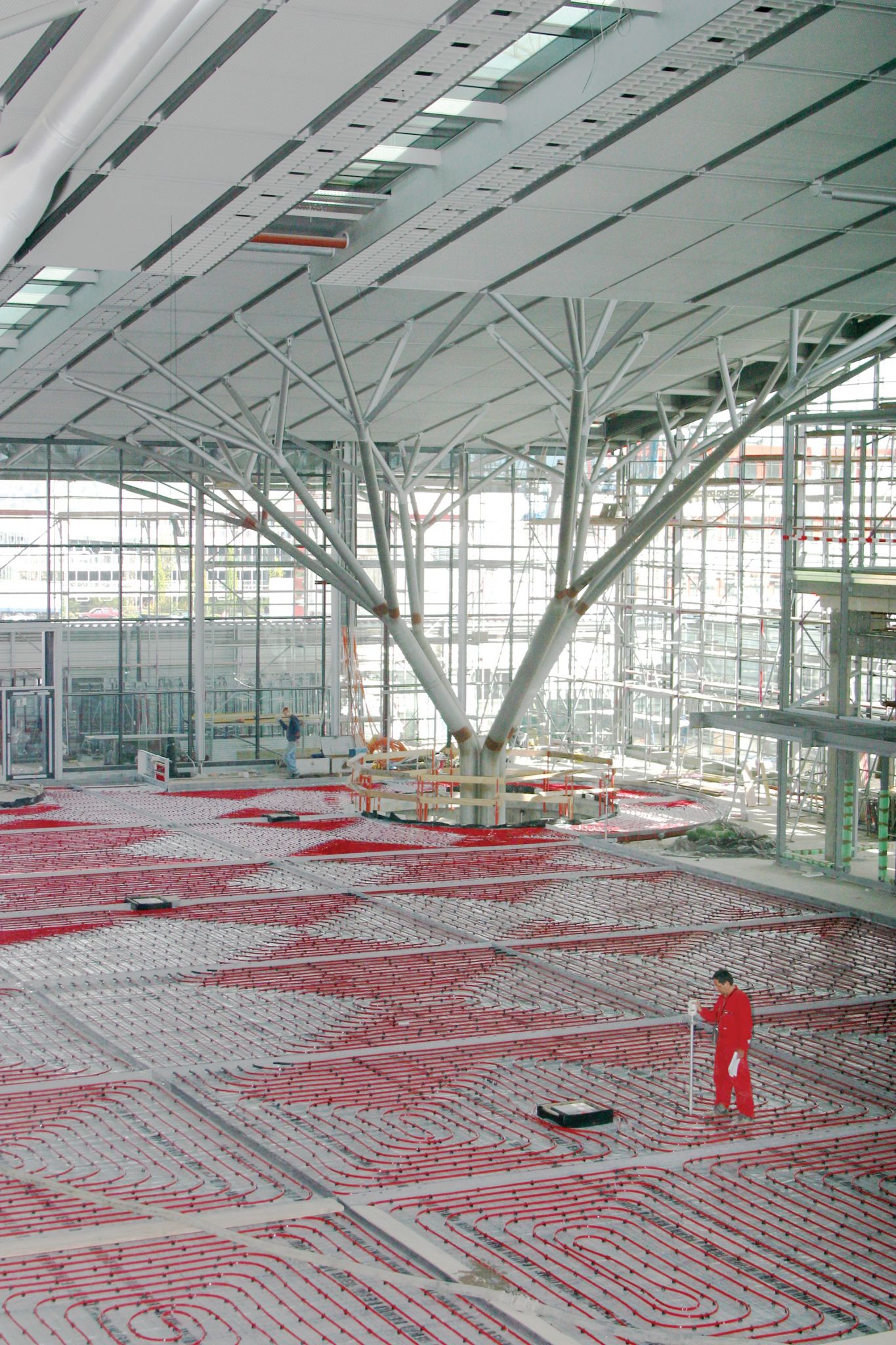
![These images show the radiant pipe layout at the Stuttgart Airport [CREDIT] Photos courtesy REHAU](http://www.constructionspecifier.com/wp-content/uploads/2015/05/Stuttgart-Airport-0000D935.jpg)
Specified air setpoint temperatures
It is important to keep in mind radiant systems should be operated with higher space setpoint temperatures in cooling mode and lower in heating mode than traditionally conditioned spaces (i.e. 100 percent forced-air systems). Since radiant systems directly manipulate the mean radiant temperature, air setpoints should be adjusted to compensate and maintain the same thermal comfort.
This means in cooling mode, air setpoints should be no less than 24 C (75 F); in heating mode, they should typically be at 20 C (68 F). While these ranges deviate from standard forced-air design practice, the addition of a radiant system maintains thermal comfort.2
Realistic locations for manifolds
In a radiant design, it is important for specifiers to agree on suitable manifold locations to balance the distribution of fluid to the various zones being served. Concerns from architects may include the visibility, or in some cases, accessibility (i.e. classrooms with access at a student’s level), of the cabinets. Concurrently, engineers are tasked with providing distribution piping and pumping schematics to provide adequate flow to these manifolds. The essential question, ‘Is the number of manifolds sufficient for the space?,’ is often neglected until the project reaches the desk of the designer tasked with drawing circuit layouts.
![Although designs of two of the latest buildings on Infosys’ campus near Hyderadad, India may look the same, one has a leg up in energy efficiency with its radiant heating and cooling system. Integrated early into the project’s design, radiant cooling helps the building maintain increased thermal comfort with a one-third reduction in energy consumption. [CREDIT] Photo courtesy Infosys Limited](http://www.constructionspecifier.com/wp-content/uploads/2015/05/Infosys-05102010091_252250_0.jpg)
Another frequently overlooked question is whether the manifolds are centrally located within the space, or isolated, for example, at the end of a long hallway. If the number of circuits is chosen solely on the zone’s area, there may be issues with the supply and return to the furthest extent of a zone. In other words, the radiant designer will run into difficulties reaching the end of the hall and returning to the manifold if the distance is greater than 46 to 61 m (150 to 200 ft).
A tell-tale sign of this problem is final shop drawings with a maximum loop pressure differential substantially greater than other circuits. Although this design can be achieved with a sufficient pipe diameter and reasonable temperature drop (or gain when operated in cooling mode), these situations tend to result in frustrating discussions and unexpected costs, since the circulating pumps may be sized for a lower head loss.
One of the many reasons radiant systems are increasingly specified is the flexibility many hydronic manifolds have to serve multiple zones. Unfortunately, if manifold locations are not coordinated with realistic understanding of the path where the circuit tails need to be routed, there can be issues.
Many times, based on structural walls, the most effective way to route tails to circuits filling an exterior zone is back to a manifold centrally located in a hallway. In this case, as shown in Figure 1, the interior hallway has lost its original intention of being a separate zone. Revisions to this design were likely needed to rectify the situation, resulting in added manifold locations, distribution piping, and possibly even pumping selection.
A strategy for mitigating condensation risk
Condensation is a fairly straightforward phenomenon. If a surface is colder than the dewpoint temperature, water condenses on the cool surface. Although this is desirable for a fan-coil when trying to remove latent energy from the space, it is not so desirable on a radiant manifold—and even worse on a radiant slab.
In most commercial buildings, protecting against the risk of condensation can be quite simple. The coolest point in the fluid’s path through the radiant circuit is, by definition, the entering water temperature at the supply header of a radiant cooling manifold. Therefore, it makes the most sense to monitor and control the system from this point. Ensuring the entering water temperature is never lower than 1.6 C (3 F) above dewpoint effectively mitigates condensation.
![In the diagram above, there is a clear design flaw in that nearly all of the project tails are required to funnel through one small hallway. Not only has the ability to zone this hallway separately been lost, but also the chance of overheating this interior space is greatly increased because external zones will call for heat first. [CREDIT] Image courtesy REHAU](http://www.constructionspecifier.com/wp-content/uploads/2015/05/CS_June_2014_HR-71.jpg)
While humidity is relatively easy to control in high-performance buildings with a curtain wall or fixed windows, buildings designed with operable windows pose challenges for radiant system control. There are successfully commissioned projects with these openings, but more engineering work may be needed to ensure the radiant systems do not run the risk of operating when windows are open—this is most important in humid climates. Relays can be installed to detect whether a window or door is left open, but it is hard to guarantee the thermal mass ‘charged with cooling’ combined with humid air flowing into the space will always operate outside of dangerous condensation risk.
Conclusion
Only 15 years ago, a radiant system capable of cooling was nearly unheard of in North America. Today, with hundreds of reference projects in nearly all climatic zones throughout the region pushing the high-performance building industry, the question is less, ‘why?’ than ‘how to get there efficiently?’ By considering some of the above design attributes, specifiers will provide better direction to the HVAC and radiant system designers and minimize design iterations. Concurrently, it will help in achieving a successful and robust hybrid radiant system. While it is always easier to continue specifying the status quo, hydronic radiant systems are definitely an option for paving the way to net-zero building construction.
Notes
1 For more, see “Getting to Zero 2012 Status Update: A First Look at the Costs and Features of Zero Energy Commercial Buildings” at newbuildings.org/sites/default/files/GettingtoZeroReport_0.pdf. (back to top)
2 For more information see this author’s, “What Does the Thermostat Say? Why Air Temperature is Just Part of the Comfort Equation,” at www.rehau.com/US_en/Construction/Blog/1341074/air-temperature-in-the-comfort-equation.html. (back to top)
Ryan Westlund is a building technology commercial project manager with REHAU North America. He serves on the Industry Advisory Board for Center for the Built Environment (CBE) as an advocate for research to further building technologies and bridge academia with industry. Westlund holds a bachelor’s of science in mechanical engineering from Rose-Hulman Institute of Technology, and is pursuing a master’s degree in sustainability management from American University’s Kogod School of Business. He can be reached by e-mail at ryan.westlund@rehau.com.


Most important of all they are safe to use, easy to install and energy efficient.
Where are you guys located??
I am trying to build a commercial building in TEXAS, and I cannot find anyone to install Hydronic heating.
Bound to be somebody that does it. Do you all work in Texas??
Bob Burnitt
Bob Burnitt: Did you ever find anyone to install the hydronics? Where in Texas are you?
did anyone find a hydronic heating installer in TX?? Maybe I need to shift fields!