

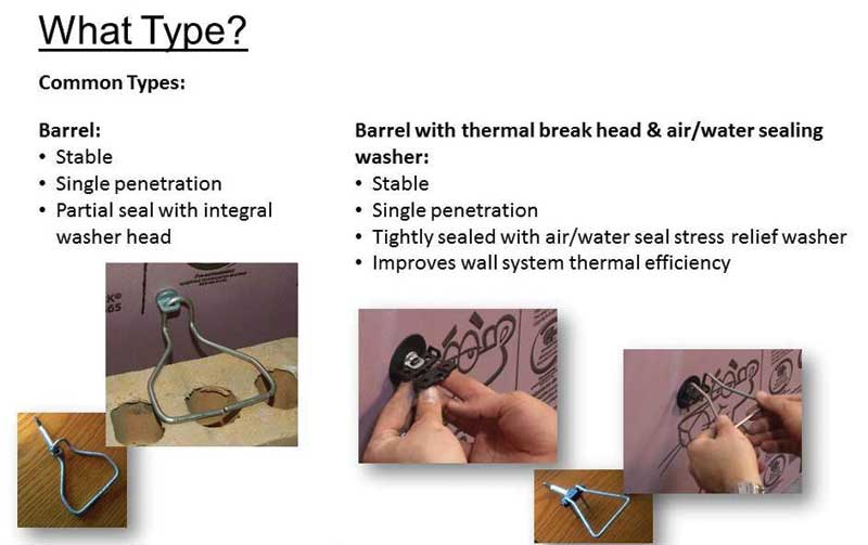
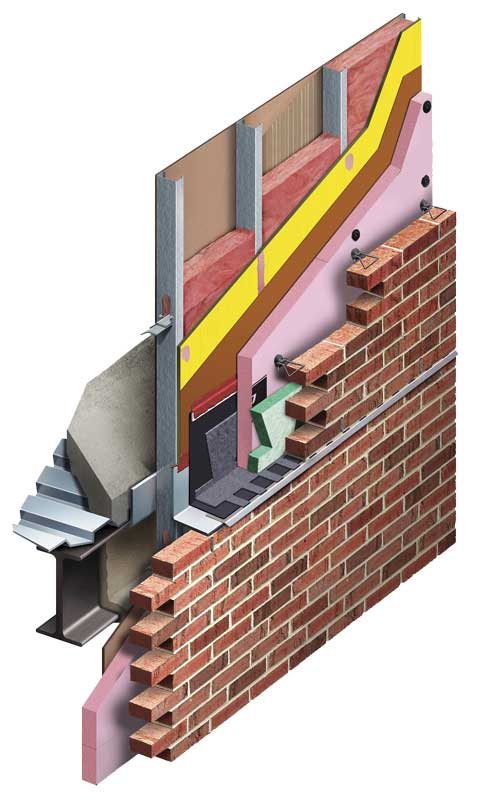
Images courtesy CavityComplete Wall Systems
Moisture management
Moisture management means not only getting water out of the wall, but also allowing air into the wall so it can dry quickly and completely. Since water infiltration poses a significant danger to walls, it is wise to take a redundant approach to moisture management. Redundancy means there are multiple planes of defense against moisture intrusion.
These multiple planes include first the watershed at the face of the cladding or veneer. Behind that is an air space encouraging water to drain out of the wall, breaking the directly connecting path for water to enter the wall. The third redundancy is the use of a highly water-resistant, continuous insulation layer such as extruded polystyrene (XPS), which will shed rather than absorb any water that makes it to the board’s face. (Another insulation option would be polyisocyanurate [polyiso]. Expanded polystyrene [EPS], sprayed polyurethane foam [SPF], and mineral wool could also be used as continuous insulation, but they are not as water-resistant as XPS.) The final line of defense is the water-resistive barrier itself, often installed behind the continuous insulation and over the exterior-grade gypsum sheathing. All of the redundant layers are a natural part of masonry veneer construction.
Water-resistive barrier
Air- and water-resistive barriers are often a single product, the same layer in the wall, which resists bulk water penetration and wind-driven rain penetrating the exterior cladding. This contrasts with vapor, which either enters the wall system by permeation or is carried into it by air leakage. In a complete wall system, depending on the regional design considerations, the functions of the air barrier, vapor barrier, and WRB are sometimes combined in one product—frequently, a liquid product that is roller- or spray-applied. Greater efficiencies can be achieved if only one trade is involved in applying the all-in-one type of product instead of multiple trades applying each of the air-, vapor-, and water-resistive barriers.
Air barriers
Air barriers have a strong influence on energy efficiency. It is estimated air leakage is responsible for about six percent of total energy used by commercial buildings in the U.S. About 15 percent of primary energy consumption in commercial buildings attributable to fenestration and building envelope components in 2010 was due to air leakage. (For more, visit www.airbarrier.org/wp-content/uploads/2017/06/Buildings-XIII_OnlineAirtightnessCalculator_V5.pdf.) Air barriers are often also weather-protective and water-resistant. They allow the building envelope to prevent accumulation of water in the building and establish a drainage plane inside the wall.
Vapor barriers
Vapor barriers control the rate at which moisture moves in and out so the wall can dry. Many variables go into choosing and placing the correct barrier. For example, should it be located on the warm or cold side of the cavity? Since vapor will always move into the wall from the high-vapor-pressure (moister)
side of the wall, and migrate to the low-pressure (drier) side, the rule of thumb is the barrier always goes on the high-pressure side. This generally means the barrier goes on the interior or ‘heated’ side in northern locations, and on the exterior ‘high humidity’ side in the south. In the middle states, vapor barrier placement and the question of whether one should be used are a bit ambiguous. In such situations, further hygrothermal evaluation should be done by a qualified expert—often consultants or insulation manufacturers—using tools considering climate, building materials, HVAC systems, and building function.
In addition to placement, it is equally critical to decide between high- or low-perm barriers. Part of the vapor management consideration also involves the absorptive capability of the other components in the wall itself. All building materials absorb water, reservoir it, and then release it as conditions change, so one must account for these conditions as well.
A good place to start researching vapor barriers is the International Building Code (IBC) Section 1405.3, “Vapor Retarders,” which has definitions of and perm ratings for vapor barriers. The higher a material’s perm rating, the more permeable it is to water vapor. A Class I vapor barrier is a material with a perm rating of less than 0.1, which is at the level of polyethylenes or trilaminates like foil scrim kraft materials. Class II barriers have a permeance of greater than 0.1, but less than or equal to one, which is typical of fiberglass facers like a foil or kraft paper facer. Finally, there are the Class III barriers, which include all barriers with a perm rating greater than one and less than or equal to 10, such as common wall paint.
When it comes to placing the vapor barrier, IBC says a wall with continuous insulation is more tolerant of moisture because it stays warmer; therefore, condensation inside the wall becomes less of a possibility. If the cladding is back-ventilated, as it is in a masonry cavity wall, the wall can dry faster and more completely, which influences the vapor barrier choice. Given there are so many interdependent variables, and because each building and region creates a dynamic and unique set of conditions, a hydrothermal analysis, such as can be provided by WUFI software, is often helpful.
WUFI allows realistic calculation of the transient coupled one- and two-dimensional heat and moisture transport in walls and other multilayer building components exposed to natural weather, enabling a full understanding of how all the layers of the wall perform together to manage vapor and air movement under thermal conditions that vary by hour over years.
In addition to understanding the way vapor barriers handle moisture, it is necessary to consider their flame spread ratings. Typically, steel stud/brick veneer construction is classified by IBC as Type I or II construction and its insulation must use a facer with a flame spread less than or equal to 25 when tested in accordance with ASTM E84, Standard Test Method for Surface Burning Characteristics of Building Materials.


I am providing a few clarifications to points about polyisocyanurate (polyiso) insulation which could be misconstrued in the article:
1. Closed-Cell: Polyiso is a closed-cell rigid foam insulation for use in roofs and walls. Polyiso wall insulation materials meet the ASTM C1289 and are an excellent choice for a continuous insulation system.
2. Moisture resistance: PIMA polyiso manufacturers test products for water absorption. For example, foil-faced polyiso insulation is water repellent due to the low impermeability of the facers and the closed cell nature of the foam core. These properties provide long-term moisture resistance. In fact, the Brick Industry Association’s Technical 28B cited by the author recognizes ASTM C1289-compliant materials as options for brick veneer/steel stud walls. The author’s use of the phrase “truly small and closed cell” in reference to XPS insulation is not recognized by a test standard and may mislead specifiers.
3. High R-Value: With polyiso you can meet the energy code requirements with less product due to the high R-value per inch of polyiso wall insulation.
Thanks for your comments, Justin. We’d like to address your points as follows:
1. Closed-Cell: The term “closed cell” is relative and has more meaning when placed in comparative context. The photos in the article show the difference in XPS versus polyiso cell structure.
2. Moisture resistance: The test standards you cite are different and thus difficult to compare. Polyiso uses a much less rigorous water absorption standard compared to extruded polystyrene. Test standard C 209 uses 2 hours of immersion with 10 minute drain time, compared to test standard C 272 which uses 24 hours of immersion with no drain time. Even still, polyiso has a higher water absorption level in C 209 versus XPS in C 272. The use of different standards, one much less rigorous than the other, is not widely realized among specifiers and leads to confusion when comparing polyiso to XPS. The information in this article sheds light on the differences. Or for more information, read this FAQ, link below:
http://www.owenscorning.com/NetworkShare/EIS/10019950-FOAMULAR-XPS-vs-Poly-FAQ.pdf
3. High R-Value: Polyiso R-values vary by manufacturer. Depending on which manufacturer’s claim is used, the difference in product thickness between polyiso and XPS to achieve an R-10 value may only be 1.75” of material versus 2”.
Further, the use of the LTTR method by polyiso manufacturers to estimate long-term thermal performance a few years ago introduced “actual” R-value uncertainty. LTTR was demonstrated to yield a positive bias in estimating long-term performance. The rigid insulation industry experienced significant debate regarding the validity and reliability of aging estimates for R-value via LTTR.
More recently, the cold weather performance of polyiso has been measured and shown to decline at cold temperatures, per the link below:
http://www.greenbuildingadvisor.com/articles/dept/musings/cold-weather-performance-polyisocyanurate
So, like water absorption, R-value claims are also subject to the need for interpretation.