

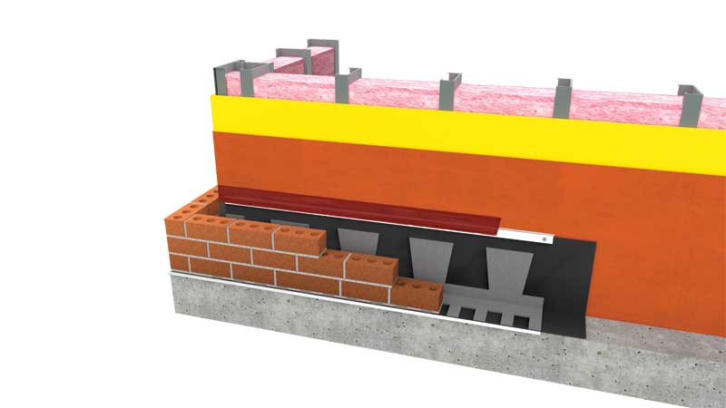
Through-wall flashing
Through-wall flashing is a three-part moisture management path consisting of a flashing membrane, mortar dropping collection, and weep vents. When properly specified and installed, this system captures and directs water out of the wall, no matter where or how water penetrates it.
A flashing membrane must:
- be attached to the sheathing;
- run continuously from the front of the brick ledge to at least 305 mm (12 in.) up the substrate;
- be behind the continuous insulation; and
- be fastened with a termination bar sealed at its top edge with a compatible sealant.
The membrane should also include a drainage mesh to prevent the possibility of mortar damming. Including a drip edge is highly recommended in order to prevent ultraviolet (UV) exposure from degrading the flashing membrane edge.
A mortar dropping collection device is the second component of the three-part moisture management path. Various techniques have been employed over the decades, but specially designed mesh products were introduced in 1992 and have become mandatory in a well-designed wall.
These products should be:
- shaped with two levels; (For example, some proprietary systems employ a two-level trapezoidal shape that breaks up and suspends mortar droppings above the flashing. This trapezoidal shape also prevents mortar dams as the top is wider than the bottom, acting as an overhang to prevent droppings from covering the entire lower level.)
- placed in a single continuous row on top of the flashing membrane at the bottom of the cavity;
- able to suspend mortar droppings on two levels to prevent mortar damming; and
- made from 90 percent open-weave mesh (allowing water to flow through the mesh to the flashing membrane and the weep vents, as well as letting air circulate through the device to promote drying).
Weep vents are the third part of the complete moisture management path. They prevent the weep holes located in masonry veneer head joints—both low at the flashing level and high near the top of the cavity—from being clogged by insects or debris. Located low, they allow water to run freely off the flashing and out of the cavity. Located high and low, they allow air to move through the cavity to enable drying. Weep vent inserts are available made from mesh that is slightly compressible so they fill the head joint, replacing the mortar so the mason need not apply mortar to fill gaps between the vent insert and masonry. They are also available in colors to match mortar choices.
It is extremely important to specify weeps that do not block the flow of water off the flashing membrane. Weeps such as tubes and some rigid weeps form a barrier at the flashing level, which means water has to rise behind them in the cavity before it can run out. Rope weeps are not recommended because they provide no ventilation and can rot over time. It does not matter how good the rest of the moisture management path is—if water cannot get out through the weeps, it will not work.
Sealants
Sealants must be compatible with all materials to which they are applied and must also be function-specific. For example, while butyl sealants are perfect for sealing overlapping materials such as flashing membrane joints because they are extremely long-lasting and aggressively adhesive, they must never be used in vertical butt joints because butyl never ‘sets’ and will ooze out of the joint. Butyl also remains ‘tacky’ throughout its lifetime, so it is not paintable, and should not be used where it is exposed and visible because it has the potential to hold dirt and debris. (The specific sealant will be dependent on the materials specified for each project. For assemblies like the one with which the authors are most familiar, a silyl terminated polymer [STP] works well due to its moisture-cure properties, color availability, and flexibility while still being compatible with any incidental asphaltic-based products in surrounding areas. Butyl will also work with many of the system’s installation procedures, including on the brick ledge, at panel overlaps, and at points where membranes overlap corners and end dams, and on top of the termination bar. Other sealant types, such as modified polyether, may also work well, but their effectiveness and compatibility can be material-dependent. A designer should always check with the manufacturer of the sealant they want to specify to ensure the chosen sealant is compatible with the other components.)


I am providing a few clarifications to points about polyisocyanurate (polyiso) insulation which could be misconstrued in the article:
1. Closed-Cell: Polyiso is a closed-cell rigid foam insulation for use in roofs and walls. Polyiso wall insulation materials meet the ASTM C1289 and are an excellent choice for a continuous insulation system.
2. Moisture resistance: PIMA polyiso manufacturers test products for water absorption. For example, foil-faced polyiso insulation is water repellent due to the low impermeability of the facers and the closed cell nature of the foam core. These properties provide long-term moisture resistance. In fact, the Brick Industry Association’s Technical 28B cited by the author recognizes ASTM C1289-compliant materials as options for brick veneer/steel stud walls. The author’s use of the phrase “truly small and closed cell” in reference to XPS insulation is not recognized by a test standard and may mislead specifiers.
3. High R-Value: With polyiso you can meet the energy code requirements with less product due to the high R-value per inch of polyiso wall insulation.
Thanks for your comments, Justin. We’d like to address your points as follows:
1. Closed-Cell: The term “closed cell” is relative and has more meaning when placed in comparative context. The photos in the article show the difference in XPS versus polyiso cell structure.
2. Moisture resistance: The test standards you cite are different and thus difficult to compare. Polyiso uses a much less rigorous water absorption standard compared to extruded polystyrene. Test standard C 209 uses 2 hours of immersion with 10 minute drain time, compared to test standard C 272 which uses 24 hours of immersion with no drain time. Even still, polyiso has a higher water absorption level in C 209 versus XPS in C 272. The use of different standards, one much less rigorous than the other, is not widely realized among specifiers and leads to confusion when comparing polyiso to XPS. The information in this article sheds light on the differences. Or for more information, read this FAQ, link below:
http://www.owenscorning.com/NetworkShare/EIS/10019950-FOAMULAR-XPS-vs-Poly-FAQ.pdf
3. High R-Value: Polyiso R-values vary by manufacturer. Depending on which manufacturer’s claim is used, the difference in product thickness between polyiso and XPS to achieve an R-10 value may only be 1.75” of material versus 2”.
Further, the use of the LTTR method by polyiso manufacturers to estimate long-term thermal performance a few years ago introduced “actual” R-value uncertainty. LTTR was demonstrated to yield a positive bias in estimating long-term performance. The rigid insulation industry experienced significant debate regarding the validity and reliability of aging estimates for R-value via LTTR.
More recently, the cold weather performance of polyiso has been measured and shown to decline at cold temperatures, per the link below:
http://www.greenbuildingadvisor.com/articles/dept/musings/cold-weather-performance-polyisocyanurate
So, like water absorption, R-value claims are also subject to the need for interpretation.