

Adjustable veneer anchors are a two-piece system, and include eye and pintle, dovetail, and slotted systems. Adjustable systems generally allow for construction of the backup assembly first, followed by later installation of a masonry veneer. Adjustable ties can also accommodate larger in-plane differential movement and construction tolerances.
When specifying and detailing lateral anchors, hot-dipped galvanized steel in conformance with ASTM A153, Standard Specification for Zinc Coating (Hot-Dip) on Iron and Steel Hardware, are required by code for exterior wall systems. In more corrosive environments or areas where wall systems are susceptible to excessive water penetration, stainless steel ties in conformance with ASTM A580, Standard Specification for Stainless Steel Wire, are recommended. Masonry wall ties should be sized to fit the width of the mortar joints and wall construction and spaced to accommodate lateral loads. Standard wire diameters for masonry ties are W1.7 (9-ga or 4-mm [1/8-in.]) and W2.8 (5-mm [3/16-in.] diameter wire). According to TMS 402/602-16, the allowable wire diameter for masonry ties is half the mortar joint width. However, given the tolerances in joint width, the smaller diameter wire may be recommended to allow for sufficient mortar coverage in a typical 9.5-mm (3/8-in.) joint. Veneer ties and anchors should be sized so that they span the cavity space and extend a minimum of half the depth of the masonry veneer unit. BIA suggests a minimum embedment of 38 mm (1 1/2 in.) with a minimum cover of 16 mm (5/8 in.) at the exterior face of the masonry veneer.
Drainage cavity
Although masonry is a highly durable material, it is not inherently waterproof. Masonry materials will absorb moisture from precipitation and only gradually dry as ambient conditions change. For this reason, a masonry veneer must be isolated from the backup construction by a cavity.
The cavity in a veneer wall system provides an avenue to drain water entering the wall system. It consists of an air space and typically a WRB, and often includes rigid insulation and a drainage mat or mortar net. Veneer ties span across the drainage cavity. The width of the air space is measured as the distance between the back of the masonry veneer to the face of the backup wall or insulation. The International Building Code (IBC) requires a specified 25-mm (1-in.) wide air space, noting the cavity may potentially be less than 25 mm, given construction tolerance. However, a 50-mm (2-in.) air cavity is recommended.
Depending on the construction of the backup wall and commonly available options for veneer ties, the maximum width of the drainage cavity can range from 114 mm (4 ½ in.) for wood and steel-framed backup walls to 168 mm (6 5/8 in.) for masonry backup walls. For wider drainage cavities, more robust and frequent spacing of veneer ties is required to transfer lateral loads.
The effectiveness of the drainage cavity depends on the continuity of the air space and WRB. Mortar bridging, resulting from excessive mortar droppings, interrupts the air space and can create avenues for water to reach the backup construction. A narrow air cavity, changes in the depth of the veneer masonry, or misalignment of insulation in the drainage cavity may promote the formation of mortar bridges. It is recommended to mechanically fasten or self-adhere the rigid insulation in the drainage cavity to the backup.
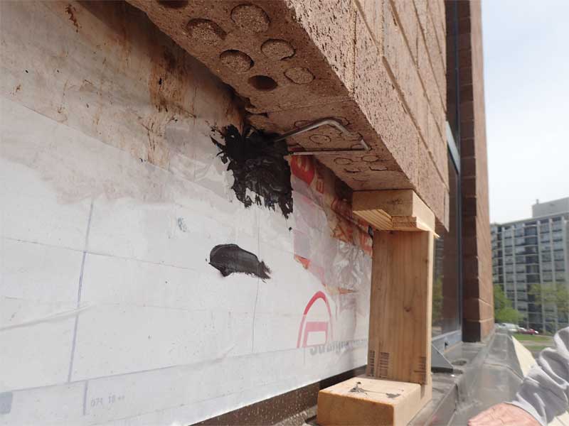
WRB is installed between the exterior wall sheathing and air space and may be liquid-applied, self-adhered, or mechanically fastened. The barrier should be free of defects such as wrinkles and open joints that may promote mortar bridging or allow water to infiltrate to the interior. If self-adhered or mechanically fastened, the edges of the membrane should be shingle lapped at least 152 mm (6 in.). Ideally, screw heads and penetrations in the WRB should be filled with a compatible sealant to maintain the continuity of the barrier. While not preferred, water-resistant facing of sheathing or rigid insulation may be used if all penetrations, edges, and joints are properly taped and sealed.
For narrower air spaces, where there is a greater probability of mortar bridging within the cavity, drainage systems such as drainage mats or mortar nets are recommended. These systems are most effective if installed the full height of the wall and can provide a clear path for movement of air and water in the wall cavity. For drainage mats, the drainage portion of the mat should face the cavity face of the masonry veneer.
Flashings and weeps
At all horizontal terminations or discontinuities in the masonry veneer construction, flashings must be provided to ensure moisture in the masonry and drainage cavity is directed to the exterior. Common flashing materials include metal (stainless steel or copper) or membrane (rubberized asphalt or butyl-based materials). Metal flashings can be made continuous by soldering adjacent sections or by lapping and sealing with butyl. Rubberized flashings are lapped and sealed with a compatible product. Although other materials, such as laminated copper flashing, asphalt-coated copper fabric flashing, ethylene propylene diene monomer (EPDM) rubber, thermoplastic, or polyvinyl chloride (PVC) are available for flashings, these may be more prone to damage during construction, and it may be more challenging to form watertight seams between sections of flashing.

