

Flashing materials in a veneer system need to bridge across the cavity to integrate with the WRB at the back of the cavity or to terminate into the substrate. At the point where the flashing crosses the cavity, flexible materials may be prone to sagging or puckering, creating valleys where water can collect. Also, it can be challenging to make the seams between flashing pieces watertight at the cavity. For these reasons, rigid metal flashings are preferred, especially as a flashing pan to span the cavity.
The front edge of the flashing should extend beyond the face of the veneer with a drip edge, so water draining from the flashing is not allowed to run back onto the masonry or other materials below. Since rubberized flashing materials are generally unstable in ultraviolet (UV) light, these flashing materials must be held back at least 12 mm (1/2 in.) from the exposed face of the veneer, and a stainless steel drip edge provided to form the termination of the flashing system. The back edge of the flashing system should be secured to the backup, typically with a termination bar and/or mechanical fasteners. If a WRB is used, the barrier materials should be lapped into the flashing assembly and fully sealed.
An end dam must be provided wherever a flashing terminates horizontally, such as at the end of a window lintel or shelf angle. Without an end dam, water on the flashing may drain from the back corner of the flashing, creating a concentration of water within the cavity that can saturate adjacent materials.
To ensure proper drainage from flashings, weeps or vents are provided. Cotton or synthetic rope wicks, either with or without plastic tubes, may be used. These types of wicks should be placed by the mason within the head joints in the first course of masonry above the flashing, and should be long enough to extend from the outer face of the veneer to the back of the cavity. Cellular plastic or aluminum cell vents sized to fit exactly within a single head joint are another option—these vents are available in a variety of colors to minimize their visual impact. Weeps should be spaced at 400 mm (16 in.) on center (o.c.).
Control and expansion joints
For masonry veneers, movement related to thermal and moisture changes are key considerations. The coefficient for thermal expansion of clay masonry as defined in TMS 402 equates to about 12 mm (½ in.) for a 30-m (100-ft) long wall experiencing 38 C (100 F) of temperature change. The equivalent value for concrete masonry is slightly higher. As a result, differential thermal movement between the materials of 1.6 to 4.8 mm (1/16 to 3/16 in.) is possible over a 30-m length.
Moisture-related masonry movements are mostly a concern related to long-term, irreversible volume changes. Clay masonry units are at their smallest size when removed from the kiln and first installed. The units will slowly and irreversibly expand over time as they absorb ambient moisture. The expansion is most rapid for the first year in service and decreases to a negligible rate after 10 to 20 years. A challenge in masonry design is that other commonly used building materials, particularly concrete and wood, experience irreversible shrinkage while in service, so the relative increase in size in a clay masonry veneer compared to the size of the underlying wood or concrete structure may be significant. For example, concrete masonry will experience long-term irreversible shrinkage due to drying.
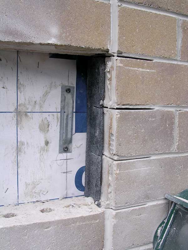
Control and expansion joints are used to accommodate movements resulting from these volume changes. Joints are also needed at changes in the architectural or structural geometry where cracks are likely to form. In veneers, vertical joints should be spaced at approximately 8-m (25-ft) intervals in walls without openings, at offsets or near building corners, door openings and window jambs, and at any joints in the underlying structure. Horizontal joints should be provided at every floor level in multistory construction. Design of control and expansion joints should extend the full depth of the masonry veneer and include a highly compressible fill material to prevent mortar and debris from clogging the joint. The minimum size of the joint needed can be determined by reference to the coefficients of thermal and moisture expansion for the various materials, the expected temperature change for the façade surface (which may be 50 C (120 F) or more), and the size of the masonry panel.
Conclusion
Contemporary masonry veneer wall systems offer flexibility of design, means of addressing water penetration, and ease of construction. They incorporate a wide range of materials and systems including masonry, mortars, masonry ties, WRBs, insulation, flashings, and control and expansion joints. As such, the effectiveness of masonry veneer wall systems is dependent on material specification, attention to design and detailing, and proper construction procedures.
Kenneth Itle, AIA, is an architect and associate principal with Wiss, Janney, Elstner Associates (WJE) in Northbrook, Illinois. He specializes in historic preservation and the assessment and repair of masonry systems. Itle can be reached at kitle@wje.com.
Mike Ford, AIA, is an architect and senior associate with WJE’s Northbrook, Illinois, office, specializing in historic preservation and the assessment and repair of existing buildings. He can be reached at mford@wje.com.
Timothy Penich, AIA, is an architect and senior associate with WJE’s Northbrook, Illinois office, specializing in historic preservation. His work also includes condition surveys and the preparation of repair documents relating to masonry and roofing and waterproofing. He can be reached at tpenich@wje.com.

