General drainage notes

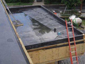
The ponded water observed in Figure 6 remains in place for several key reasons, including the primary and secondary internal roof drains are improperly situated in relationship to the drainage cricket and the rear outer perimeter parapet wall.
At the high point or widest section of the drainage cricket, the waterway measures approximately 2.4 m (8 ft) out from the parapet wall at the far corner of the image. However, at the low point or the narrowest section of the drainage cricket, the waterway measures approximately 1.2 m (4 ft) out from the parapet wall at the near corner of the photograph, thereby compromising the effective slope of the drainage cricket by at least one-half.
Consequently, this drainage cricket is undersized to a degree that it does not meet the requirement of being twice the slope of the finished roof with a 13-mm (½-in.) minimum slope. As a result, the undersized cricket only displaces the ponded water up the slope of the roof instead of directing it into the primary roof drain.

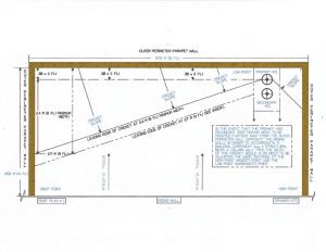
Proper design and installation would mandate the drainage cricket must have a slope measuring at least twice the slope of the roof along with well-defined waterways constructed out of tapered polyisocyanurate (ISO) rigid insulation board. Figure 7 illustrates the consequences of improperly designing and/or installing the drainage cricket. In this drawing, the internal primary roof drain is located away from the outside parapet wall by approximately 0.3 m (1 ft). Due to this condition, it would be necessary to extend the high point or widest portion of the cricket by the same dimension, which, in this case, would be 0.3 m (1 ft), bringing the total measurement at the widest point of the drainage cricket to 2.7 m (9 ft). The low point or narrowest portion of the cricket must be 0.3 m. Otherwise the effective slope of the cricket would be compromised by the difference between these two dimensions so as to maintain the 2.4-m (8-ft) requirement at the cricket’s highest point. This design is accepted as good roofing practice among industry professionals, with the goal to get the water off the roof especially when the slope is minimal in many areas of this roof.
This concept would hold true regardless of the distance of the roof drain from the parapet wall, provided the aggregate measurement remained the same proportionately at both ends of the new drainage cricket (e.g. if the drain was set at the dimension of 1.2 m [4 ft] from the near corner of the outer perimeter parapet wall, then the cricket at the far corner of the outer perimeter parapet wall must be 4.4 m [12 ft]).
Also, the project design team must always take into consideration the addition of the tributary area of rising walls adjacent to and above the roof structure. This information would allow them to properly calculate the size of the drainage system. It is pertinent to note the secondary roof drain must be a minimum of 50 mm (2 in.) above the finished surface of the completed roof system assembly.
Alleviating misconceptions
Having a well-designed and properly installed low-slope roof featuring an internal roof drainage system will require an in-depth assessment of all conditions prior to addressing onsite challenges one may encounter during installation. Things to remember include:
- base curb flashings on RTUs must meet the 210-mm (8-in.) minimum height requirement;
- additional primary drains cannot be cut into the roof at random locations without ruling out the presence of trapped water between two discrete systems;
- the presence of materials with asbestos in the existing roof system must be ruled out;
- new internal primary and secondary roof drains can be connected to an already existing drain pipe system, provided the latter is in sound condition and sized properly to drain the expected volume of water;
- the performance of a roof scan to qualify the presence of any latent water trapped within the existing roof system or systems; and
- it would be necessary to determine the type of roof deck that is on the building (i.e. metal, concrete, or lightweight concrete, etc.), the condition of the existing roof condition of the existing roof deck, if possible, and if the steel infrastructure is sloped or level.
To ensure the best possible outcome of the project, all of these items must be properly evaluated, and the findings verified and provided to the design team prior to developing an action plan.


