Better drainage, better low-slope commercial roof systems
by nithya_caleb | May 29, 2019 12:00 am
by Anthony J. Katona, CDT
 [1]
[1]According to the National Roofing Contractors Association (NRCA) and nearly all single-ply roof membrane manufacturers, the term ‘ponded water’ can be defined as “any accumulation of water that remains on the surface of the completed roof system 48 hours after the last rainfall.” ‘Standing water’ refers to any remaining water that will evaporate before 48 hours after the last rainfall.
The intention of this article is mainly to provide insight on the many important elements of proper drainage on low-slope commercial roofs, exclusively those with internal primary and secondary roof drainage systems, and the impact they have on effectively eliminating ponded water conditions.
 [2]
[2]Images courtesy Alliance Roof Consultants, Inc.
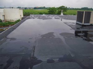
While there are many benefits of having a well-drained low-slope commercial roof system, two significant advantages are that of roof structural safety and the prevention of premature deterioration of the roof system. For these reasons, one thing this author evaluates during a roof audit is how well the roof drains. Or, in other words, has the roof been designed and constructed to alleviate ponded water? Proper drainage cannot be emphasized enough when discussing or reviewing the requirements of any well-drained low-slope commercial roof system (Figure 1).
The building in Figure 2 is located in the mid-Atlantic region near a large city on the East Coast. The building was unoccupied at the time of a cursory audit. The main concern was the lack of adequate drainage. In the author’s experience, this condition of ponded water is more prevalent when a roof system is installed over an existing one—this idea is supported by the two discrete edge metal details visible in Figure 2.
Consequences of ponding
 [3]
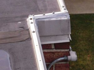
[3]It has long been recognized by construction industry professionals, including forensic structural engineers, architects, building envelope and commercial roof consultants, and plumbing engineers specializing in designing a roof system with internal primary and secondary roof drains, the primary cause of failure is excessive water ponding.
According to Roof Drainage, published by the Roof Consultants Institute Foundation (RCIF), “With a density of 28 kg (62.5 lb)/cf³, water is a heavy substance. A 25-mm (1 in.) depth of water adds a weight of 2.3 kg (5.2 lb)/ft² on the roof. The design live load for a typical roof is 9 kg (20 lb)/ft², and the building codes allow for a reduction in this figure so that the structural elements with large tributary areas can be designed for a live load of only 5.4 kg (12 lb/ft²).” (For more information, read the Roof Consultants Institute Foundation’s [RCIF’s] Publication No. 20.03, Roof Drainage.)
For economic reasons, this live load reduction is often invoked in the structural design of a roof deck assembly, particularly long span roofs. Unfortunately, this limit can be exceeded by the weight of only 6 mm (2.5 in.) of ponded water—a poorly drained roof can accumulate this much water fairly quickly during heavy downpours with disastrous results such as:
- roofing bitumens have certain compounds that dissolve under the sustained pressure of standing water, thereby reducing the membrane’s life; and
- some adhesives used in single-ply membranes deteriorate under similar conditions.
Although many of the new adhesives manufactured and used today are scientifically more advanced and the room for workmanship-related errors is lessened, there are more concerns about temperature (i.e. too cold or hot) and high humidity levels during the various stages of application.
There is no debate that a well-designed, well-constructed, and well-drained roof system outperforms a roof exhibiting poor drainage. Since proper drainage is important, most of the commercial roof manufacturers will not issue a no-dollar limit (NDL) warranty on projects without removing all existing roofing material, and installing a completely new system from the roof deck up. Alternatively, a disclaimer may be added stating the exclusion of coverage in areas where ponding occurs.
In the example of a re-roofing project, a cover board is typically placed between the existing roof and the newly installed system. However, moisture trapped between the roof membranes either in the form of liquid, solid, or gas causes certain types of roof insulations (e.g. fiberglass, wood-fibered, and/or perlite) to deteriorate and compress, resulting in the creation of low spots throughout the field of the roof.
 [4]
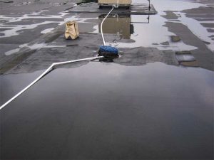
[4]In Figure 3, a single roof drain was observed to be at an elevation higher than the adjacent roof area, thereby preventing proper drainage. This situation could be exacerbated by the lack of an adequate amount of strategically positioned and/or properly sized internal roof drains, in addition to zero slope of the roof in these areas.
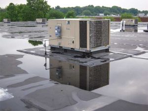
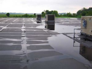
A lack of well-defined waterways are also interrupted by rooftop units (RTUs) and thus limiting the options available to properly address ponding (Figure 4). For instance, structural steel support beams are likely installed directly under the area where the mechanical
 [5]
[5]equipment is mounted to the roof. In the author’s experience, this would almost always include the presence of other structural and/or mechanical elements on the interior of the building. This could limit the ability to install additional roof drains, complete with primary and secondary drainage components and a tapered rigid insulation drainage cricket system, at the roof deck’s low point where ponded water is most prevalent.
In this case, the feasibility of properly connecting additional primary and secondary roof drains in a specific building depends on several factors such as:
- location and height of building;
- actual ceiling height;
- existence of a suitable network of drain conductors and vertical and horizontal drainpipe lines; and
- applicable building and plumbing codes.
Roofs with minimal slopes present additional challenges. For example, it is likely there is only 3 to 6 mm (1/8 to ¼ in.) per foot slope or zero slope in many areas of the roof in Figure 3. The height of the base curb of the RTU would be substantially compromised by the installation of tapered rigid insulation crickets. One of the solutions would be to temporarily remove all RTUs’ roofing material and design a temporary fix with new drains and crickets to try to reduce the amount of ponded water. However, this measure would not be recommended by the author because water trapped between two discrete roof systems can leak when one cuts through to the top of the roof deck.
 [6]
[6]As observed in Figure 5, the installation of additional new internal primary roof drains would not eliminate ponding, as the underdeck steel infrastructure and related mechanical equipment would require the construction of drainage crickets. These crickets must be large enough to create adequate slope from one side of the low point to the other side to offset the existing slope of the roof so as to direct the water runoff into the primary roof drains instead of simply displacing it higher up the slope.
However, this plan would be contingent on attaining the appropriate building permits and complying with the locally adopted building and plumbing codes. Depending on the project’s location, its use, and the codes adopted by the authorities having jurisdiction (AHJ), the addition of new internal roof drains could fall short of the intended purpose because some plumbing codes now require the installation of an independent secondary roof drainage system.
General drainage notes
 [7]
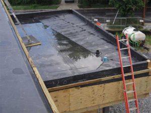
[7]The ponded water observed in Figure 6 remains in place for several key reasons, including the primary and secondary internal roof drains are improperly situated in relationship to the drainage cricket and the rear outer perimeter parapet wall.
At the high point or widest section of the drainage cricket, the waterway measures approximately 2.4 m (8 ft) out from the parapet wall at the far corner of the image. However, at the low point or the narrowest section of the drainage cricket, the waterway measures approximately 1.2 m (4 ft) out from the parapet wall at the near corner of the photograph, thereby compromising the effective slope of the drainage cricket by at least one-half.
Consequently, this drainage cricket is undersized to a degree that it does not meet the requirement of being twice the slope of the finished roof with a 13-mm (½-in.) minimum slope. As a result, the undersized cricket only displaces the ponded water up the slope of the roof instead of directing it into the primary roof drain.
 [8]
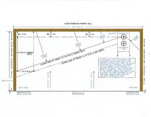
[8]Proper design and installation would mandate the drainage cricket must have a slope measuring at least twice the slope of the roof along with well-defined waterways constructed out of tapered polyisocyanurate (ISO) rigid insulation board. Figure 7 illustrates the consequences of improperly designing and/or installing the drainage cricket. In this drawing, the internal primary roof drain is located away from the outside parapet wall by approximately 0.3 m (1 ft). Due to this condition, it would be necessary to extend the high point or widest portion of the cricket by the same dimension, which, in this case, would be 0.3 m (1 ft), bringing the total measurement at the widest point of the drainage cricket to 2.7 m (9 ft). The low point or narrowest portion of the cricket must be 0.3 m. Otherwise the effective slope of the cricket would be compromised by the difference between these two dimensions so as to maintain the 2.4-m (8-ft) requirement at the cricket’s highest point. This design is accepted as good roofing practice among industry professionals, with the goal to get the water off the roof especially when the slope is minimal in many areas of this roof.
This concept would hold true regardless of the distance of the roof drain from the parapet wall, provided the aggregate measurement remained the same proportionately at both ends of the new drainage cricket (e.g. if the drain was set at the dimension of 1.2 m [4 ft] from the near corner of the outer perimeter parapet wall, then the cricket at the far corner of the outer perimeter parapet wall must be 4.4 m [12 ft]).
Also, the project design team must always take into consideration the addition of the tributary area of rising walls adjacent to and above the roof structure. This information would allow them to properly calculate the size of the drainage system. It is pertinent to note the secondary roof drain must be a minimum of 50 mm (2 in.) above the finished surface of the completed roof system assembly.
Alleviating misconceptions
Having a well-designed and properly installed low-slope roof featuring an internal roof drainage system will require an in-depth assessment of all conditions prior to addressing onsite challenges one may encounter during installation. Things to remember include:
- base curb flashings on RTUs must meet the 210-mm (8-in.) minimum height requirement;
- additional primary drains cannot be cut into the roof at random locations without ruling out the presence of trapped water between two discrete systems;
- the presence of materials with asbestos in the existing roof system must be ruled out;
- new internal primary and secondary roof drains can be connected to an already existing drain pipe system, provided the latter is in sound condition and sized properly to drain the expected volume of water;
- the performance of a roof scan to qualify the presence of any latent water trapped within the existing roof system or systems; and
- it would be necessary to determine the type of roof deck that is on the building (i.e. metal, concrete, or lightweight concrete, etc.), the condition of the existing roof condition of the existing roof deck, if possible, and if the steel infrastructure is sloped or level.
To ensure the best possible outcome of the project, all of these items must be properly evaluated, and the findings verified and provided to the design team prior to developing an action plan.
Installation practices
 [9]
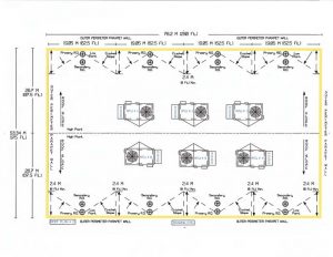
[9]As mentioned earlier, when the roof slopes from the high point to the low section and toward the outer perimeter parapet walls, the leading edge of the tapered rigid insulation board must extend a minimum of 2.4 m (8 ft) out from the inside face of the parapet (Figure 8). This creates a footprint for the crickets that make up the well-defined waterways and provides a way for the elimination of rainwater through the primary roof drains.
In this example, the primary and secondary roof drains are set perpendicular to the parapet walls at the low point of the roof structure. The tapered rigid insulation boards are positioned so the point of entry is directed into the center of the primary roof drains. The secondary roof drains must be elevated a minimum of 50 mm (2 in.) above the finished surface of the completed roof system assembly.
Typically, certain codes require the conductors and horizontal and vertical drainpipes of the secondary roof drains to be plumbed independently and discharged through the exterior wall of the structure at a height between 1.5 and 2.4 m (5 and 8 ft) above ground level. This way, if rainwater is visible to occupants of the building and/or a passerby, it would indicate the primary roof drains are not functioning as intended.
Limitations
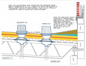 [10]
[10]Figure 9 illustrates the components of a well-designed and properly functioning internally drained roof system (contingent on having the roof drains, conductors, horizontal piping, and drainpipe lines sized properly). Briefly, the components of a primary and secondary roof drain assembly include the underdeck mounted cast iron clamps (used to secure the drain bowl to the roof deck, a cast iron ring clamp assembly (utilized to secure the roof membrane to the drain), and a cast iron strainer basket.
In Figure 9, the first item to recognize is the 6-mm (¼-in.) per foot slope of the roof deck is created by sloping the steel infrastructure, which is likely to be the least expensive and most functionally sound method, from a good roofing practice perspective. Additionally, there are two discrete layers of ISO rigid insulation board, installed with the edges offset in both directions by a minimum of 152 mm (6 in.) to prevent thermal bridging. Depending on the specifications, they may be simultaneously mechanically fastened to the metal roof deck. The secondary drain is positioned a minimum of 50 mm (2 in.) above the surface of the completed roof system assembly.
The tapered rigid insulation fill and board, making up the well-defined waterways throughout the roof, must be built to a point to create a cricket measuring twice the slope of the roof deck, with a 13-mm (½-in.) minimum slope.
In the author’s experience, it can be problematic to use lightweight concrete and tapered ISO insulation board during the time of installation, especially in cold climates. The roof deck must be perfectly flat to achieve the required slope for tapered rigid insulation board systems. Additionally, cost would be a determining factor depending on the actual overall thickness of the ISO material making up the roof substrate. Also, depending on the overall thickness at the highest point of the insulation, it could get built-up pretty quickly. For example, in the author’s experience, tapered insulation plans are very much a function of thickness at the high points (with a requirement that it is designed to be installed on a flat metal roof deck). At times, it was observed the screws were 610 mm (24 in.) long to secure the insulation to the steel roof deck. This condition typically occurs on large low-slope commercial buildings. Further, temperature and humidity restrictions exist if some types of expanding sprayed-in-place adhesives are specified for use.
Temperature restrictions, high-wind consequences, and curing time are all factors to consider when using lightweight concrete. The temperature must be above 4.4 C (40 F) for 48 hours prior to and after placing the material. Additionally, if there are high winds during the application, the finished surface could be significantly impacted and uneven much like the surface of water is during high winds, depending on the speed of the winds and the height and location of the building. Also, curing time requires up to 48 hours or more of set up time—this can be affected by wet weather after the initial application, and prior to the installation of the new roof system.
Conclusion
Even though the internal drain system is more expensive than other methods, the benefits far overshadow the difference in initial cost, especially when one considers ruling out the premature deterioration and failure of the roof system selected to protect the building and the structural integrity of the roof deck. However, the most important element is the safety of the occupants.
When all elements of planning, designing, and constructing a low-slope commercial roof with internal primary and secondary roof drains come together, it provides a water handling system with low maintenance, high function, and extended value as the assembly will most likely last until the building structure is decommissioned.
| REFERENCES |
| ● Roof Drainage, authored by Steven Patterson, PE, RRC, Medan Mehta, PhD, and J. Richard Wagner, PE, and published by the Roof Consultants Institute Foundation (RCIF). ● The Manual of Low-slope Roof Systems by C.W. Griffin and Richard Fricklas. ● International Building Code (IBC), 2009. ● Factory Mutual (FM) Global, “Property Loss Prevention Data Sheets,” October 2012. ● The Importance of Proper Roof Slope, by Mark S. Graham. ● InspectAPedia – Roof Drainage Requirements & Specifications. |
Anthony J. Katona, CDT, is president of Alliance Roof Consultants Inc., and has been providing professional services as a building envelope and commercial roof consultant since 1999. With more than 30 years of construction experience, he has an extensive background in determining the source of unwanted moisture migration within troubled buildings. Katona has served as president of the Delaware Valley chapter of the Roof Consultants Institute, now known as RCI, Inc. He has also served as a member of the Editorial Advisory Board of The Construction Specifier. Katona can be reached at alliancerc@comcast.net[11].
This article is for informational purposes only. Katona does not warrant or assume any liability for the accuracy, completeness, and/or fitness of the article for any project, and readers are strongly advised to utilize their professional experience, knowledge, and judgment, in using the information contained in this document.
- [Image]: https://www.constructionspecifier.com/wp-content/uploads/2019/05/bigstock-182589859.jpg
- [Image]: https://www.constructionspecifier.com/wp-content/uploads/2019/05/Photo-1.jpg
- [Image]: https://www.constructionspecifier.com/wp-content/uploads/2019/05/Photo-2.jpg
- [Image]: https://www.constructionspecifier.com/wp-content/uploads/2019/05/Photo-3.jpg
- [Image]: https://www.constructionspecifier.com/wp-content/uploads/2019/05/Photo-4.jpg
- [Image]: https://www.constructionspecifier.com/wp-content/uploads/2019/05/Photo-5.jpg
- [Image]: https://www.constructionspecifier.com/wp-content/uploads/2019/05/Photo-6.jpg
- [Image]: https://www.constructionspecifier.com/wp-content/uploads/2019/05/Figure-7-page-XX.jpg
- [Image]: https://www.constructionspecifier.com/wp-content/uploads/2019/05/Figure-8-page-XX.jpg
- [Image]: https://www.constructionspecifier.com/wp-content/uploads/2019/05/Figure-9-page-XX.jpg
- alliancerc@comcast.net: mailto:alliancerc@comcast.net
Source URL: https://www.constructionspecifier.com/better-drainage-better-low-slope-commercial-roof-systems/