Breaking it down: Keys to diagnosing glass breakage in buildings
by sadia_badhon | August 20, 2019 3:00 am
by Steven D. Marino
 [1]
[1]Its beauty can turn heads. From the functional to the fantastic, glass delivers on numerous levels in contemporary building designs—aesthetics, performance, quality, and energy efficiency, to name a few. It is no wonder architects make it the centerpiece of building designs. As the focal point of high-visibility structures, expansive glazing areas and large insulating glass units (IGUs) take more space on curtain walls, storefronts, and interior building components than ever before. Despite the numerous appearance and performance advantages, glass has a breaking point.
Primary causes of glass breakage
Although a relatively rare occurrence, the breakage of glass post-installation in high-rise buildings raises several questions beyond just the immediate need to replace the unit(s). Was it a one-time event, or part of a pattern of similar breaks in a particular glass product? Did the glass shatter into hundreds of pieces or simply crack? Was the glass properly installed? What role did weather play?
Although these questions are typically part of a more in-depth investigation, any incident always demands an answer to this fundamental question: Why did the glass break?
Like many brittle materials, glass, whose compressive strength is higher than its tensile strength, breaks or fails when stresses approach or exceed the material’s limits. Simply put, when an external force applied to a glass exceeds its maximum strength, the product fails.
A prevalent contributing factor of breakage is edge damage. Even minor defects on the edge of a glass panel can reduce its strength by more than 50 percent, compromising its ability to resist both thermal and mechanical loads.
 [2]
[2]Images courtesy Vitro Architectural Glass
Although edge damage in and of itself does not break the glass—after all, the material may remain functional throughout its service life—it creates a weak point that may make the glass susceptible to conditions increasing the likelihood
of breakage.
In some instances, the cause of breakage can be traced to inclusions, which can be non-homogenized, or not fully melted, batch materials or contaminates such as nickel and aluminum. Two types of inclusions are nickel sulfide (NiS) and aluminum oxide (Al2O3) ‘stones.’
Many inclusions ‘behave’ the same way glass does—they expand in heat and contract in cold. Although most inclusions do not directly cause breakages, their size, composition, and location are the primary factors in the small percentage of inclusion-related incidents that actually occur.
Identifying the break origin
When there is a pattern of repeated glass breaks, it is critical to explore the reasons for such incidents. Typically initiated by the building owner or glazing contractor, this investigation should begin with identifying the origin of the break. This is possible only if pieces of the broken glass can be retained or re-assembled into the original orientation.
Identifying the break origin can provide hints about the following:
- mode of glass failure—is it mechanical or thermally induced stress;
- the stress or tension level at which the breakage occurred; and
- other contributing factors—were there digs (deep, short scratches) resulting from glass-to-glass or glass-to-metal contact, did a projectile hit the glass, or is there edge or surface damage?
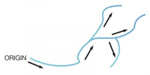
To find the origin of a break, the first step is to assess its direction by inspecting the fracture lines, or ‘Wallner lines,’ in the glass. These rib-shaped marks, distinguished by a wave-like pattern through the thickness of the glass, begin at the break origin and radiate along break branches. The marks (or wave-like pattern) almost always concave in the direction from which the crack was propagating. The concave side of the wave is the origin and the convex section is the direction of propagation of the fracture.
 [3]
[3]It is helpful to make a basic diagram of the fracture lines as viewed from the surface in a plan view (Figure 1). This can be easily done by examining the direction of the Wallner lines on the edges of individual pieces of glass. The origin of the break can be determined by:
- drawing arrows (indicating fracture line direction as viewed from the surface plan view) pointing toward the concave face of break wave markings in the glass edge; and
- tracing point-to-tail of arrows back to the break origin.
Failure modes
Knowing the origin of the break sets the stage for determining the mode, or type, of failure. The lack of crystallographic planes in glass can allow certain break patterns to be observed and then associated with modes of failure. Two common modes are mechanical and thermal.
Mechanical stress
The most common contributing factor of breakage, mechanical stress occurs when forces resulting from bending or impact exceed the modulus of rupture (MOR), a critical metric in stress analysis. There are low- and high-stress mechanical tension breaks.
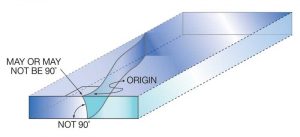
 [4]
[4]Low-stress tension breaks are experienced most frequently by the manufacturers residential windows and IGUs. The origin of the break is typically at damaged areas of the edge or surfaces near the edge, such as digs, scratches, or chips. In many cases, in-service breakage of marred glass occurs after the initial edge damage is incurred, such as during IGU fabrication, sashing operations, transportation, jobsite handling or storage, or the installation process.
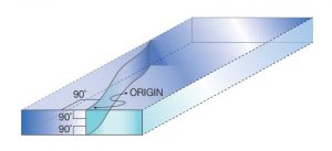
In Figure 2, the break origin is not 90 degrees to the edge of the glass, indicating a tension break caused by bending. Low-stress, mechanical tension breaks often occur from bending at less than 10,342 kPa (1500 psi).
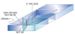
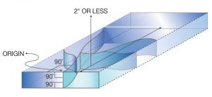
High-stress tension breaks share one characteristic with the low-stress ones—the break origin is not 90 degrees to the edge of the glass, suggesting a tension break caused by bending. However, additional branching of the crack within 50 mm (2 in.) of the break origin indicates the stress at breakage was likely higher than 10,342 kPa (Figure 3).
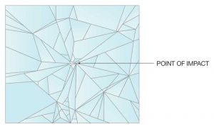
High-stress breakage due to impact at the glass edge or surfaces near the edge is typically the easiest to identify, as multiple fractures emanate from the point of impact in a spider web fashion (Figure 4). This breakage pattern is a tell-tale sign that either the glass edge or surface was struck by a foreign object with significant force.
Thermal stress
Thermal stress results from several factors including weather, the method of glass installation, and the insulation around the material. Breaks caused by thermal stress occur because of large temperature differences, most commonly between the edge and center of the glass. For instance, when the sun hits the glass and warms up its center, but the edges remain cold, the thermal gradient produces increased stress, potentially leading to breakage. This temperature gradient can be even more severe when glass is glazed into concrete and other heavier framing. These materials act as a heatsink keeping the edges cooler for a longer period of time. Thermal stress breaks often originate at the edge of the glass and form virtually 90-degree angles to the edge and surface of the glass.
 [5]
[5]As with mechanical stress, there are two types of thermal stress breaks: low- and high-stress.
Low-stress thermal breaks are often indicated by a single break line starting at the break origin point at or near the glass edge and propagating 50 mm or more before branching into more break lines (Figure 5). Damaged glass edges are the most frequent cause of low-stress thermal breakage.
High-stress thermal breaks appear as a single break line starting at the break origin point at or near the glass edge and generally branch into additional breaks within 50 mm of the origin (Figure 6). This indicates a breakage brought on by conditions causing high thermal stress such as:
- severe outdoor shading on parts of the glazing;
- heating registers located between the glass and indoor shading devices;
- closed, light-colored drapes located close to the glass; or
- glazing in massive concrete, stone, or similar framing.
It is important to note most thermally induced stress breaks in architectural glazing applications occur in the winter, when it is colder overnight, and the low-angle morning sun heats the center of the glass more quickly than the edges.
Analyzing the break origin
 [6]
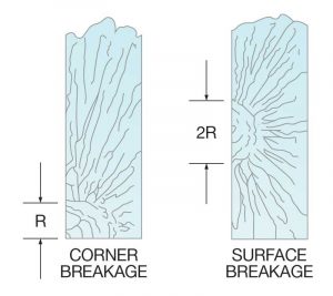
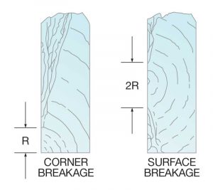
[6]A reliable method for estimating the stress level of a break at failure is a mirror radius (defined in ensuing paragraphs) measurement. Radius dimensions are determined by crack propagation velocity characteristics.
A crack propagates itself through glass with increasing velocity as it moves further from the point of origin. If an object has sufficient energy to propagate a crack through the thickness of the glass, then a spider web pattern will form. The lack of crystallographic planes in glass causes this type of crack to proceed perpendicular to the applied tension stress.
Near the point of origin, a smooth, mirror-like appearance on the fracture face indicates a low crack velocity. However, as velocity increases (due to higher tension stress), the fracture face takes on a frosted look. Then, at the highest velocity, it assumes a ragged or hackled appearance.
Mirror radii appear in various forms, depending on the stress level of the fracture. Figure 7 shows break origins resulting from high tensile stresses, such as bending or thermal stress breaks.
Figure 8 represents the break origins of glass fracturing at low bending stresses. In this example, a smooth fracture face forms across the thickness of the substrate. When the breaking stress is low, the mirror radius is often radial and may extend deeply into the substrate.
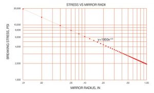
The relationship of the radius of the mirror surface of the break origin to the stress that caused the breakage is expressed by the following:![]() [7]A deeper dive
[7]A deeper dive
The graph in Figure 9 also shows the radius-to-stress relationship at various levels of breaking stress.
 [8]
[8]In some situations, it is helpful to expand the investigation beyond determining the type of breakage and the stress level of the break. Pinpointing the actual source of the damage can help prevent or reduce future occurrences of breakage.
For example, a lite of glass might appear to have been broken by high, thermally induced stresses, when, in fact, a more-detailed analysis might reveal impact damage that reduced the thermal-loading threshold of the glass may have been the actual cause.
To identify what damaged the glass in the first place, four factors are examined during this analysis including:
- impact;
- inclusions;
- thermal variance; and
- pressure differentials.
Impact
Identifying the nature of the breakage pattern can determine whether a foreign object hit the glass and if the impact was perpendicular or parallel.
Depending on the severity of the impact, the immediate area surrounding the break origin might be cracked, crushed, or missing (Figure 4).
 [9]
[9]Other sources of impact can be detected during the fabrication process or the transit and installation of the glass—these usually appear at the edges. As mentioned previously, edge damage can reduce the strength of the glass by more than 50 percent, thus increasing the likelihood of breakage due to mechanical and/or thermal stress.
Inclusions
Any undesirable material embedded in glass is considered an inclusion. Coming in numerous shapes and sizes, inclusions such as NiS and Al2O3 stones can have unlimited distribution densities. These densities factor into the glass quality ratings by ASTM C1036, Standard Specification for Flat Glass. Quality for clear glasses ranges from Q1 (used in the production of high-quality mirrors) to Q6 (applications in which blemishes are not a concern).
Contaminates in batch materials and furnace refractory degradation are often contributing factors of inclusions. Sometimes, however, an inclusion might consist of only unmelted batch material. Regardless of the source, responsible glass manufacturers go to great lengths to ensure inclusions are kept to a minimum. However, since the raw materials are mined from the earth, no known technology will totally eliminate the rare occurrence of nickel- or aluminum-related inclusions.
Effects of NiS inclusion
Similar to water, NiS increases in volume as it cools. The presence of NiS inclusion in the center residual tension stress region of thermally tempered glass can lead an investigator to believe the breakage occurred spontaneously. In reality, the breakage was likely caused by a phase transformation that increased (from two to four percent) the volume of the inclusion. This growth caused additional stresses, likely leading to the breakage.
Here is how this could happen. When float glass is manufactured, the glass is intentionally cooled at a slow, controlled rate to minimize or eliminate residual surface, edge compression, and center tension. During this process, called annealing, inclusions can undergo a phase transformation (α to β) and become stable without causing breakage.
When the glass is reheated during heat strengthening or full tempering, any existing NiS stones will shrink to their smaller, high-temperature stable α form. The slower cooling cycle used to make heat-strengthened glass allows the stones to complete this phase transformation. The author’s firm is unaware of a single confirmed case of spontaneous breakage of heat-strengthened glass due to NiS stone inclusions.
In contrast, the rapid cooling cycle used to produce fully tempered glass stops the phase transformation, thereby trapping the stones before they complete their volume growth. This can become problematic later when a glass is in-service and its temperature exposure restarts the phase transformation, triggering the volume growth of NiS stones and re-instigating conditions leading to breakage. Due to potential phenomenon, the author has a long-standing preference for the specification and use of heat-strengthened glass, except where tempered glass is mandated for safety or by code.
Thermal variance
 [10]
[10]Another potential underlying factor contributing to breakage is thermal variance, which could be caused by interior and exterior shading. If the temperature difference across a lite of glass is great enough, the accompanying stresses can reach breakage-causing levels. This is particularly true if the nucleation point of the crack was caused by a damaged edge or an inclusion. In this case, the break origin is often located near the edge of the glass.
The characteristics of tinted and spandrel glasses (higher heat absorption) and glass glazed into large concrete or steel structures (edges stay cooler longer) may contribute to the intensity of thermal-variance stresses in these applications.
Additionally, temperature variations could enable an IGU to partially collapse or, in other words, the glass plies bend inward. Since an IGU is sealed around the edges, as the air inside the unit is cooled, it condenses, reducing the pressure possibly allowing the glass plies to become closer together. This IGU glass collapsing may produce conditions with potential impact on thermal-variance stresses. For instance, with a collapsed IGU, there is often contact between the glass and muntin bars inside the window or between the two pieces of glass. This can create an alternative path for heat conduction, thereby establishing localized temperature gradients. The combination of contact, surface damage, and localized gradients can greatly increase the likelihood of breakage.
Pressure differentials
When the assembly and installation of an IGU occurs in two different places, a variation of altitude—even as little as 1524 m (5000 ft)—that changes atmospheric pressure, can jeopardize the unit’s integrity, causing the seal to rapidly fail and potentially lead to breakage.
 [11]
[11]Studies show altitude changes of only 305 m (1000 ft) accompanied by large temperature differences between the installation and assembly sites can cause IGU failures after extended periods of time. This is exacerbated at higher temperatures—when the temperature differential exceeds 21 C (70 F), as each 11 C (20 F) differential increase is equivalent to an altitude increase of 305 m.
Glazing contractors can offset this risk by installing capillary tubes to regulate pressure changes in IGUs. The tubes must be properly terminated at the final location by crimping or sealing to prevent moisture ingression. Since capillary tubes allow for gases to enter and exit the IGU, gas filling must be done at the final installation site to maintain pressure equilibrium. Care should be taken if the IGU includes a magnetron sputter vapor deposition (MSVD) low-emissivity (low-e) coating because moisture ingress during transportation and storage when the tube is open can be detrimental to the coating.
It is important to research framing systems and IGU spacers when altitude and temperature changes are factors.
Conclusion
In its pristine state, glass, as a prominent element in architectural design, can define contemporary buildings. However, sometimes glass breaks for no obvious reason. Whether it is a one-off or part of a continuing pattern of incidents, glass breakage is inconvenient, potentially dangerous and costly for building owners, construction professionals, and other stakeholders.
Although architectural glass and fenestration manufacturers continue to develop advanced technologies to make their products as ‘break-proof’ as possible, absolute perfection is simply impossible due to flaws inherent in the glass-manufacturing process and the wide range of in-service environments in which the material must ultimately perform.
Conducting ‘postmortems’ on glass breaks can help investigators identify the general reasons for each incident, including the type of failure causing the break, and the potential source of damage.
By using the techniques outlined in this article, building owners, contractors, engineers, glass manufacturers, and other stakeholders may be able to accurately identify the likely origin of failures. Doing so would have the advantage of placing more emphasis on the opportunity to use the information in design. A really good outcome of this article would be for the design team to learn to prevent conditions increasing the risk of breakage.
Steven D. Marino is manager of technical services for Vitro Architectural Glass (formerly PPG Flat Glass). Marino has more than 30 years of experience in automotive and architectural glass. He has held positions in manufacturing, quality, and other technical roles. He holds a bachelor of engineering degree in mechanical engineering from Youngstown State (Ohio) University. Marino is an active participating member of the Insulating Glass Manufacturers Alliance (IGMA) and National Glass Association (NGA)/Glass Association of North America (GANA). He also sits on multiple committees and task groups for both organizations. Marino can be reached at smarino@vitro.com[12].
- [Image]: https://www.constructionspecifier.com/wp-content/uploads/2019/08/ENT-06_final.jpg
- [Image]: https://www.constructionspecifier.com/wp-content/uploads/2019/08/2017015_Vitro_GlassBreakage_Illustrations_5.23.18-03.jpg
- [Image]: https://www.constructionspecifier.com/wp-content/uploads/2019/08/2017015_Vitro_GlassBreakage_Illustrations_5.23.18-07.jpg
- [Image]: https://www.constructionspecifier.com/wp-content/uploads/2019/08/2017015_Vitro_GlassBreakage_Illustrations_5.23.18-09.jpg
- [Image]: https://www.constructionspecifier.com/wp-content/uploads/2019/08/2017015_Vitro_GlassBreakage_Illustrations_5.23.18-02.jpg
- [Image]: https://www.constructionspecifier.com/wp-content/uploads/2019/08/2017015_Vitro_GlassBreakage_Illustrations_5.23.18-01.jpg
- [Image]: https://www.constructionspecifier.com/wp-content/uploads/2019/08/2017015_Vitro_GlassBreakage_Illustrations_5.23.18-10.jpg
- [Image]: https://www.constructionspecifier.com/wp-content/uploads/2019/08/2017015_Vitro_GlassBreakage_Illustrations_5.23.18-06.jpg
- [Image]: https://www.constructionspecifier.com/wp-content/uploads/2019/08/2017015_Vitro_GlassBreakage_Illustrations_5.23.18-04.jpg
- [Image]: https://www.constructionspecifier.com/wp-content/uploads/2019/08/2017015_Vitro_GlassBreakage_Illustrations_5.23.18-08.jpg
- [Image]: https://www.constructionspecifier.com/wp-content/uploads/2019/08/2017015_Vitro_GlassBreakage_Illustrations_5.23.18-05.jpg
- smarino@vitro.com: mailto:smarino@vitro.com
Source URL: https://www.constructionspecifier.com/breaking-it-down-keys-to-diagnosing-glass-breakage-in-buildings/