Building healthcare in a coastal environment
by brittney_cutler | June 8, 2022 9:00 am
 [1]
[1]By David L. Heuring, AIA, CCCA; Mitchell Elliott, AIA; Scott Horn, AIA; and Joshua Storm, PE
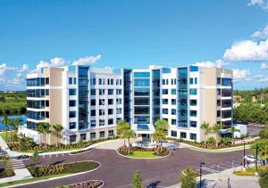
In early 2018, RDG Planning & Design and its partner firms began design work to replace an existing, nearly 50-year-old healthcare facility on the Shell Point Retirement Community campus (a Continuing Care Retirement Community [CCRC]) in Ft. Myers, Florida. Borne out of a necessity created by aging-in-place residents, but also from a desire to provide world-class service, the owner acknowledged the time is now to build for the future.
This growing market is recognized all over the country. The number of Americans ages 65 and older is expected to grow approximately 40 percent in the next 20 years. And the majority are going to retire where they live. While a small percentage of retiree’s move to a new location, the majority live in the areas in which they worked[2].
Forty percent of the U.S. population, or approximately 127 million people, live in coastal communities.[3]
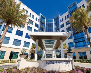
Culminating with a grand opening in early 2022, the Larsen Health Center brings together all of Shell Point’s healthcare services, including a comprehensive medical office center, behavioral health suite, therapy rehabilitation center, dental offices, pharmacy, and a 180-bed skilled nursing facility with private rooms.
 [4]
[4]In addition to the challenges inherent in designing and building any facility, Larsen Health Center had its own set of unique, site-specific needs. The design had to be responsive and resilient to coastal weather events while taking advantages of the amenities of beautiful coastal views and tropical surroundings.
The new facility is six-stories with mixed occupancy use—a 3252 m2 (35,000 sf) medical office building and a 14,864 m2 (160,000 sf) skilled nursing facility (SNF)—and located within one mile of the Gulf of Mexico coastline. Its location is on an originally poorly drained site of fine sand and muck elevated at only 2.1 to 2.4 m (7 to 8 ft) above sea level and is prone to 290-km/h (180-mph) hurricane winds and Category (CAT) 5 storm surge flooding to 8.2 m (27 ft) above sea level. It was constructed through two active hurricane seasons. Designing within these constraints proved difficult, but not impossible. Understanding the fundamental challenges of building in a coastal environment can help teams create solutions that maintain the safety of occupants, even amid extreme weather events.
Healthcare market trends
Over the last two decades, the healthcare market has undergone major shifts from institutional care models to residential/home care models. This transformation of philosophy has modified business structure, partnership alliances, and financial organization.
“Very few CCRCs are making investments in skilled nursing, but we’re bullish on it,” says Shell Point president and CEO Martin Schappell. “Locating all medical services within one facility accelerates access to care, enhances collaboration in treatment, and hastens the healing and restorative process.”
 [5]
[5]The current pandemic has pushed this evolution a step further, requiring a reassessment of operational capabilities from retaining staff and finding skilled new hires to coping with supply chain issues, and even compliance with expanded regulatory requirements and oversight. All these items inwardly affect how a healthcare facility operates. However, the chief driver of progress is a more educated and selective patient/resident base, whose concerns and expectations scrutinize level of care, quality of life, and aesthetics of ‘their’ space. As a result, facilities need to look towards holistic centered models.
Challenge of wind speeds and loads
 [6]
[6]Coastal areas are associated with hurricane wind speeds but also susceptible to lesser-wind storms and higher-wind tornados, both of which can be devasting to buildings and structures. Structural components, exterior opening protections (windows, doors, louvers), roofing, and exterior cladding need to meet stringent requirements for resistance to these forces. Applicable code items comprising wind design include wind speeds, risk category based upon use and occupancy—ranging from I (low hazard to human life in event of failure) to IV (essential facilities), wind exposure (B, C, and D), applicable internal pressure coefficient, and design wind uplift pressure.
There are two design methods used to determine wind loads: allowable stress design (ASD) and ultimate design (strength design). Winds speeds (V) can then be determined and translated to pressure (P) on the building and/or structure in pounds per square foot. ASD values (Vasd) are obtained from a conversion of the basic wind speeds (V) values.
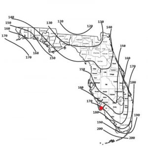
Wind speed contour maps and roof design zones
The International Building Code (IBC) and the American Society of Civil Engineers ASCE-7 standard (referenced by IBC) both contain Wind Speed Maps and requirements pertaining to wall and roof design zones used to figure pressure and suction wind loads on the structure, affecting structural member spacing, roof/deck thickness, and fastener and seam reinforcement requirements. These wind loads are associated with wind in general, whether from a storm or hurricane event. ASCE does not directly address tornado wind speed design but does include commentary guidance for designing structures and buildings to minimize damage from these events, including a simplified tornado factor (TF) for recommended adjustments to design pressures used for calculations.
 [7]
[7]Even though listed wind speeds have decreased in most regions of the United States over the last 10 years, it is important for design professionals to know and specify the correct basic wind speed (especially in coastal areas where the contours are closely spaced) and to match it to the correct risk category to ensure competent code compliance and accurate budget, cost, and constructability detailing.
Florida specific: High velocity hurricane zone (HVHZ) and wind-borne debris regions (WBDR)
After CAT-5 Hurricane Andrew hit Florida in 1992, the State enacted new specific Florida Building Codes (FBC) modeled after IBC, including adding a defined high velocity hurricane zone (HVHZ). Today that zone encompasses only Miami-Dade and Broward Counties along the Atlantic Ocean, as well as the Florida Keys. HVHZ have design wind speeds ranging from 251 to 322 km/h (156 to 200 mph) depending on location and risk category of the building. Other areas that are within 1.6 km (1 mi) of the coast where the ultimate design wind speed (UDWS) exceeds 209 km/h (130 mph) or in any areas where the UDWS is greater than 225 km/h (140 mph) are in WBDR.
 [8]
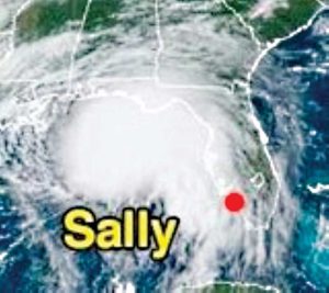
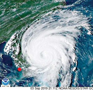
[8]Hurricane speeds typically published in news reports are categorized by the Saffir-Simpson Hurricane Wind Scale, showing sustained wind speeds. The five categorizations can be found at weather.gov/mfl/saffirsimpson.
It is important to note this scale’s sustained wind speeds are not the same as code required design wind speeds used in the design of building structures and components which are given as three-second gusts, higher than the corresponding sustained winds.
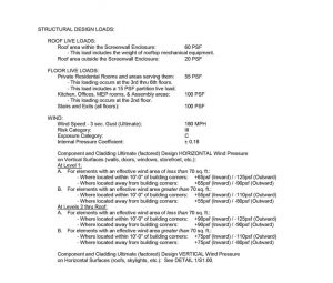
Code requirements for Larsen Health Center’s occupancy type and site location required a design of Risk Category III/Exposure C to resist three-second gusts (ultimate) wind speeds of 290 km/h (180 mph) which equate to approximately 253 km/h (157 mph) sustained winds.
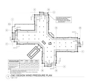
A wall pressure chart and roof design zone map were developed based upon ASCE 7 guidelines, and in conjunction with specific requirements of the FBC Structural Design Chapter (16), used to specify roofing, exterior wall cladding, and exterior window and door design wind pressure requirements.
The use of a reinforced concrete structure and exterior concrete masonry unit (CMU) walls, aluminum storefront windows with impact glazing, and Florida/NOA (Miami-Dade Notice of Acceptance) approved products and installations for exterior openings (more on this below) provide this building the strength, security, and integrity needed to withstand wind forces through Category 4 Hurricanes.
Challenge of storm surge design
Coastal areas are also associated with flooding caused by storms, torrential rains, hurricanes, and even natural drainage issues. Flooding causes as much, if not more, damage than high winds, as well as increased safety concerns and reconstruction issues. Access by first responders may be delayed due to inundated access roads, debris, and dangerous power outages, all which affect re-supply of essential vendors and establishments.
What happens with this water?
A NASA-led study of 2017’s Hurricane Harvey’s flooding of Southeast Texas with more than 1.5 m (5 ft) of rainwater, the wettest recorded hurricane in U.S. history, “…determined in the first eight days post-landfall, 30 percent of Harvey’s stormwater was captured or stored on land—most as standing water that sits on the surface. Around 60 percent was lost or drained into the ocean and Galveston Bay over the first few days after the storm, and the remaining 10 percent was lost via evapotranspiration (ET), or a combination of evaporation and plant transpiration,” said first author Chris Milliner of NASA’s Jet Propulsion Laboratory in Pasadena, California.
In arguably the most famous flood in history, Noah waited more than 150 days for floodwater to recede, 47 days to find dry land, and 57 days to disembark from the Ark.
 [9]
[9]Survey and Sea, Lake, and Overland Surges from Hurricanes (SLOSH) information
Most site elevations are referenced to North American Vertical Datum 1988 (NAVD 1988) or to National Geodetic Vertical Datum of 1929 (NGVD 29). The difference between the two, from a conversion standpoint, varies depending on the site. Most codes will require building floors to be at a certain base flood elevation (BFE) and, may in fact, require them to be 0.3 to 0.6 m (1 to 2 ft) higher, depending on use and occupancy. The Sea, Lake, and Overland Surges from Hurricanes (SLOSH) is a numeric computer model, developed by the Federal Emergency Management Agency (FEMA), United States Army Corps of Engineers (USACE), and the National Weather Service (NWS) to predict storm surge driven heights using various historical, atmospheric, topographic, and wind field data. The elevations are given in NAVD 1988 and reference the elevation above ground (sea) level. The map below indicates storm surge basins—the reasonable upper bound of potential flooding of normally dry land—unsurprisingly affecting coastal areas.
 [10]
[10]Project specific: Lee County, Florida
The County Authorities Having Jurisdiction (AHJ) requires all Healthcare SNF buildings to have a ground floor grade elevation at BFE +0.6 m (+2 ft), and all other buildings to be at the BFE +0.3 m (+1 ft) for the site location (each site varies). The FBC has a more stringent requirement for SNF’s, as indicated in this code reference:
FBC 449.4.2.2.1
Except as permitted by Section 1612 of this code, the lowest floor of all new facilities shall be elevated to the base flood elevation as defined in Section 1612 of this code, plus 2 feet, or to the height of hurricane Category 3 (Saffir-Simpson scale) surge inundation elevation, as described by the Sea, Lake, and Overland Surge (SLOSH) from Hurricanes model developed by the Federal Emergency Management Agency (FEMA), United States Army Corps of Engineers (USACE), and the National Weather Service (NWS), whichever is higher.
For this site, the first floor of the SNF needed to be at a minimum elevation of +5.5 m (+18 ft) as the ground was 2 to 2.4 m (7 to 8 ft) above sea level.
The design concept was to place the SNF over the medical office building (MOB), which presented separate challenges with the Agency for Health Care Administration (AHCA), the Florida state agency which regulates and licenses healthcare facilities. The owner desired to have the SNF entirely above the Category 5 SLOSH level for the site. Using a 4.2 m (14 ft) floor-to-floor height for the MOB (B and A-2/A-3 occupancies) placed the SNF (I-2) first floor at a +8.4 m (+27.8 ft) to meet the goal.
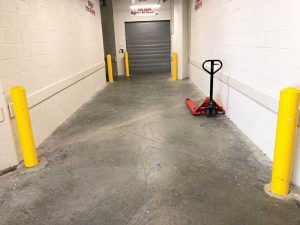
One of the FBC’s requirements for a SNF is to have a covered, grade-level entry. Putting the SNF above grade required AHCA’s acceptance of an alternate method and means. A covered Porte-Cochere main entry through the MOB and a separately enclosed, dedicated service entry at grade level for the SNF (which would incur only minimal damage during a flood event and quickly return to service when flood waters recede) helped secure AHCA approvals for locating the SNF in this coastal flood area.
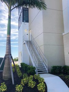
Another component added was an emergency access exterior stairway to the second level of the building (first floor of the SNF) to ensure access if the site around the grade level was flooded.
Challenges of building materials/methods
Coastal environments present unique challenges for proper design use of building materials, as well as timing and sequencing of construction, to combat humidity and moisture, harsh sunlight, rainy seasons, corrosive salt, and flooding. Several building components, products and construction methods helped address these demands.
Product approvals and roofing design information
For buildings located in HVHZ and WBDR’s, the state of Florida requires a product approval for certain materials and assembly systems. So, what is required to be protected? In HVHZ, the whole building envelope; in WBDR, exterior glazed openings (windows and doors) and ventilation openings. Typically, exterior door assemblies and roofing products and installations are also required by AHJ’s to have a Florida product approval. One of these is a notice of acceptance (NOA), a Miami-Dade County local product approval issued under applicable rules and regulations governing the use of construction materials. Florida also has a product approval database of tested products, assemblies, and installations.[11]
Roof systems are typically designed using an ASD value, which is equal to the ultimate design value multiplied by a reduction factor of 0.6. This result is then often doubled as a safety factor to provide the design wind uplift resistance loads. When roofing systems are tested by listing agencies, most agencies typically include this safety factor in the testing, so it does not need to be applied to published design wind uplift pressures. The tested wind resistance (a.k.a. the ‘wind rating’) should be higher than the design wind resistance shown on the drawings.
Choice of methods
Dewatering
Temporarily lowering groundwater levels to allow for construction and excavation activities is a common procedure for sites with high ground water levels. There are various techniques, from open sump pump immersion to ejection systems. A Wellpoint system was selected for this project as a cost-effective, manageable way to lower water levels for the site utility installations. It used an above-grade pump to generate a vacuum suction to pull water up into a header pipe and carry it to permitted, approved locations. Groundwater can be lowered approximately 6 m (20 ft) with this technique.
Vibro-floatation
Subsurface soils exploration revealed an underground makeup of soft sand, soft limestone, and local ‘muck’—not uncommon for coastal areas saturated with salt and brackish water. A geotechnical engineer was consulted for recommendations for a pile foundation selection. Various pile options include, but are not limited to, bored/cast-in-situ, driven pre-cast, and micropiles (with steel casings). A vibro-floatation foundation system was chosen due to its advantages of simplicity and speed, and cost-affordability. It did not require excavations of materials or management of water table issues and could be performed without harming existing building structures. This method improves the soil strata by injecting air and/or water through probe jets to liquefy the soil, and then uses probe vibrations to densify the soil, creating a void that is filled with crushed stone which is compacted as the probe is slowly removed. The design was delegated to a qualified sub-contractor, and the installation consisted of 367 stone piles, 0.9 m (3 ft) in diameter were injected, ranging in depth from 3 to 7 m (10 to 24 ft), and compacted to resist 287 kPa (6000 psf) loads, and were placed to support the spread concrete grade beam footings. This system improved the soil using its own characteristics, was environmentally friendly, and will reduce the possibility of differential settlements of the building’s structure.
 [12]
[12]Concrete and masonry
A reinforced, poured-in-place concrete and masonry structure was selected due to its resistance to high winds and flood water loads, local labor supply availability, and performance as an excellent substrate backing for exterior stucco finishes. Mix designs were developed to achieve desired 27,579 kPa (4000 psi) or higher concrete strengths, placement of reinforcement was meticulous and heavily inspected, and methods and schedule of concrete placement was carefully coordinated to include night-time pours. A total of 1152 tons (1045 tonnes) of rebar and 7535 m3 (266,085 cf) of concrete went into the structure.
Waterproofing, joint sealants
Various products with proven success in the Southwest Florida environment were considered. For below grade concrete, options include both liquid and membrane waterproofing systems. Liquid membranes are applied similarly to paint and are most effective for smooth surfaces and for smaller and more intricate work. Multiple coats can be applied, but care must be taken to provide an even application. Membranes are applied as elastomeric or plastic sheets that are bonded to the substrate with cement mortar or adhesive and are lapped at seams. Sheet membranes are commonly used in larger areas, and where backfilled against, are covered by a protection board product. As an alternate (or additional) method of waterproofing concrete, a crystalline admixture can be added to the concrete. This admixture product creates a crystalline structure inside the concrete, and where there is a presence of water, reacts with the byproducts of cement hydration, and becomes resistant to extreme hydrostatic pressures. In addition, at the intersection of horizontal and vertical surfaces in concrete work, a water-stop product made from rubber, vinyl, or bentonite should be used to seal the joints against water penetration. The final design choices included self-adhered, rubberized asphalt/polyethylene sheet membranes (for walls) as the primary waterproofing, crystalline waterproofing admixtures added to the concrete mix (for underground cast-in-place concrete footings, walls, and pits) as primary and secondary waterproofing, and bentonite water-stops at joint intersections. The combination of these products provided some duplicity and overlap coverage while eliminating the need for intricate work.
Exterior wall openings in CMU and concrete structures are particularly susceptible to water permeability and migration issues. Products that coat the perimeter surfaces of these openings which are specifically made to prevent this vapor drive and absorption include typical concrete/masonry water-proofers and specifically formulated liquid flashings that can be applied by either spray, brush, or trowel methods. The advantage of the product use is that it creates a weather resistant, fully adhered air barrier membrane around these openings. The design choice included a troweled on, fluid-applied liquid flashing product that proved to be compatible with the joint sealants tested in the mockup.
Joint sealant choices should be based on a number of factors, among which are environment, performance, material compatibility, joint width. The design choices of urethane acrylic and polymer elastomeric sealants were ultimately based upon proven products for the Southwest Florida environment, sealants that exhibit superior adhesion and bond strength, durability, and elongation, and compatibility performance with other materials in the mockup testing.
 [13]
[13]Roofing
Appropriate choices for roofing must include qualities of longevity, weather resistance and energy efficiency. The building design of the roof contemplated a flat structure that houses many mechanical pieces of equipment. The choices considered by the design team included BUR (built up roofing), modified bitumen (MB), and single-ply membranes. BUR systems consist of alternating layers of hot bitumen (asphalt) with layers of roofing felt that can then accept a reflective coating to combat the harsh heat and ultraviolet (UV) radiation effects of the sun. BUR’s have a typical life span of 12 to 20 years but can last up to 40 years with proper maintenance. MB systems are like BUR’s but are lighter weight (per square foot) and utilize layers of asphalt that are modified with other materials like polymers and fiberglass for increased durability. MB systems can be put down hot or ‘cold’ (as a self-adhering compound.) These can be single or multiple layers with average life spans ranging from 10 to 12 years, but up to 25 years depending on maintenance. Single-ply systems include TPO (thermoplastic polyolefin) and polyvinyl chloride (PVC) membranes which are low maintenance, energy efficient, and reliable against water and high winds. A 1.5-mm (60-mil), white color, thermoplastic polyolefin (TPO) membrane over lightweight concrete and expanded polystyrene (EPS) insulation was selected to provide an energy efficient and NOA compliant roof system.
Exterior paint
Both sun and moisture work against the exterior finishes of buildings. With a wide choice of materials from which to choose, stucco was the design choice of material to apply over the CMU and concrete structure due to its vernacular history, compatibility, and skilled tradesmen labor pool. Stucco can be painted with basically three types of paint—acrylic, elastomeric, and masonry. An acrylic paint has a high permeability rate, allowing it to dry the quickest, stretch, and prevent bubbles from forming under the surface. An elastomeric paint is thicker, and while applied as a liquid, it dries as a layer of rubber. It bridges cracks in the wall and is the most waterproof choice. Masonry paint is specifically designed to bond to masonry surfaces like stucco (and stone and brick) but is limited in color choices. A high-build, premium acrylic latex paint system was specified for this project, which combines the benefits of the acrylic and elastomeric paints. Application of primer and finish coats to the manufacturer’s specified mil-thickness provided a flexible, easily cleanable surface with superior weather resistance to wind-driven rain, mildew and organic growth, and is extremely durable in color retention.
Mockups
Exterior envelop leakage failure occurs primarily at intersections of differing materials. Detailing of the union of these materials is important, but choice of product and proper installation of materials are tantamount to success. Field built mockups of the most susceptible joints were conducted, integrating and testing different materials such as the cold-fluid applied waterproofing, aluminum frame windows, paint finishes, and backer—rods and sealants to ensure proper adhesion and performance.
Challenges of evacuation
The owner is an established but growing continuing care retirement community (CCCR) campus of approximately 2500 residents occupying 283 ha (700 acres) situated along the Caloosahatchee River near Sanibel Island and Ft. Myers Beach. The site is in a coastal high hazard area. They have six independent living facilities (ILF), three assisted living facilities (ALF), one skilled nursing facility (SNF), and one hurricane shelter (parking garage).
Defend-in-place strategy
The owner has historically provided an onsite, single-building hurricane shelter option for residents during state or county issued evacuation orders. This option utilized a two-level parking structure, designed for 322 km/h (200 mph) winds, but located only at the Category 2 flood elevation. It was outfitted with shutters to close off all exterior openings. Artificial lights, no windows, exposed concrete floors, and access to minimal restroom facilities… not the ideal place to spend 24-hours much less three or more days. In addition, there are numerous logistical issues with transferring residents from existing living places throughout this 283-ha (700-acre) CCRC to this shelter.
The broader Lee County community has 20 storm shelters (six are FEMA approved), mostly schools, and serves a population of more than 800,000 people. Not all shelters, though, are opened during events—the decision being based upon the severity of the storm event. In 2017, Hurricane Irma (with a 10-15 storm surge prediction) forced more than 34,000 people and 1000 pets to seek shelter, and 14 buildings were opened. A more difficult task is the ability to staff, open, and prepare these shelters—the County maintains a list of about 200 volunteers, the Red Cross has about 400 volunteers, and the schools typically have volunteers.
In consultation with County AHJ authorities, the Campus developed a Community Emergency Management Plan (CEMP) which included a fall-back, defend-in-place strategy which outlined procedures for safely sheltering residents on campus. While not prohibiting Group II Health Care Facilities from being located inside High Hazard Coastal areas, it is the local County Emergency Management Authorities preference that if they are, they be constructed essentially to meet FEMA Hurricane shelter requirements. These requirements include. among other items (described below), designing to 322 km/h (200 mph) or higher wind speeds and elevation of the structure to Cat 5 storm surge levels. Ultimately, they agreed to approving the CEMP for a Defend-in Place structure designed to the current County Zoning wind speed requirements (290 km/h [180 mph]) and elevated above the Building Code referenced storm surge (SLOSH) height elevations (CAT 1 for MOB, CAT 3 for SNF), as this would equal or be in excess of currently existing onsite facilities as well as offsite community option standards.
SNF as a Shelter with full Electrical power backup and Emergency Access
The SNF portion of the facility (floors 2 through 6) was designed as a defend-in-place building, to remain occupied and fully operational during weather event emergencies. Air conditioning, ventilation, vertical transportation, food service equipment, electrical lighting and power, and nurse call/IT/communication systems are fully backed up by generators sized at 400kW (natural gas for the MOB) and twin 1000kW (diesel fuel source for the SNF). The SNF generators are required by the FBC to have a 96-hour fuel supply backup power. Each generator has a ‘belly’ tank under the generator to hold the fuel supply. The requirement assumes full electrical load use during this period. Operating at a reduced load capacity, which is a more likely scenario, would allow the generator fuel supply to last seven to nine days, more than the five days requested by the Emergency Management Authority.
Water/ice supplies and first aid medical equipment
Another AHJ requirement is provide independent onsite supply or onsite storage capability of potable water supplies for all residents and staff. Quantities include 14 L (3 gal) per resident per day, and 4.5 L (1 gal) per staff per day, for up to five days. On this project, this need is meet by using either the building water supply system, or if incapacitated, by collapsible fabric ‘bladder’ tanks, which range in size from 13,638 to 954,679 L (3000 to 210,000 gal), which can be placed on-grade (large tanks) or on the roof (small tanks.) In addition, ‘adequate’ first aid medical supplies are to be stored on site (determined by the director of nursing).
Impact glass in windows
Construction guidelines for healthcare facilities located in Coastal High Hazard Areas suggest minimizing the amount of exterior glass. All glazed openings must also be provided with impact protection in accordance with the building code. The use of impact glazing, conforming to building component and cladding wind load requirements, allowed for providing larger windows that maximized the expansive views and natural daylight, resulting in a much more desired design than a closed-up concrete shelter.
External emergency communication standards
The building was designed with an Emergency Responder Radio System (ERRS), also known as a BDA (Bi-Directional Amplification system) to comply with local fire department standards. This system allows for uninterrupted radio communication within the building, eliminating ‘dead zones’ that may be created by the concrete structural systems used to resist ultra-high wind loads. It also allows for an exterior direct line-of-sight communication with the 411 radio tower serving the county. The building has a communication system inside that allows for independent zone and/or building wide messaging.
Sheltering capacity
The defend-in-place strategy was planned not just for the 180 residents and applicable staff of the SNF but assumed other scenarios of sheltering up to totals of 482, 632, and 925 occupants. Each scenario provided a ‘layout of resident homes’ to separately keep independent living, assisted living, skilled, and memory care residents together in the building to maintain their sense of community and maintain familiarity with their ‘neighbors’ should an event require.
Conclusion
The future is quickly closing in on us. In 2030, all of the baby boomer generation will be older than age 65. U.S. Census figures indicate that “…one in every five residents will be retirement age,” by that decade.
This aging population does not want their ‘grandfather’s Buick’ when it comes to retirement/healthcare facilities. They are looking for home versus institutional and hospitality-like environments that will allow them to live life with choice, dignity, and style. Design and construction of needed healthcare buildings in coastal environments can overcome the risks associated with the areas to serve this growing population’s evolving desires.
Author
 David L. Heuring, AIA, CCCA, LEED AP, NCARB is a partner with RDG Planning & Design, and works primarily in the senior living architecture market as a contract administrator and project manager. He assists the design team contributing code research, design critique, consultant coordination, construction detailing, and quality assurance/quality control, and works with owners and contractors from schematic design through the completion of construction to deliver successful, on-time, and on-budget projects. He has 32 years combined experience as a licensed architect and design-build contractor. He can be reached at dheuring@rdgusa.com.
Contributors
Scott C. Horn, AIA, NCARB, is a partner with RDG Planning & Design, and works primarily in the senior living market as a senior project architect. He can be reached at shorn@rdgusa.com.
Joshua Storm, PE, is an Engineer with Thompson, Dreessen & Dorner Inc. (TD2), and specializes in structural engineering. He can be reached at JStorm@TD2CO.com.
- [Image]: https://www.constructionspecifier.com/wp-content/uploads/2022/05/0.1_Larsen-Health-Center.jpg
- worked: http://cnbc.com/2015/11/06/most-retirees-stay-put-but-those-who-move-head-here.html
- coastal communities.: http://oceanservice.noaa.gov/facts/population.html.
- [Image]: https://www.constructionspecifier.com/wp-content/uploads/2022/05/1.02b_FBC-Wind-Speed-Map-Risk-Category-III_FIGURE-1609.3.jpg
- [Image]: https://www.constructionspecifier.com/wp-content/uploads/2022/05/1.02c_Sally_NOAA_HR.jpg
- [Image]: https://www.constructionspecifier.com/wp-content/uploads/2022/05/1.02d_Dorian_-NOAA.jpg
- [Image]: https://www.constructionspecifier.com/wp-content/uploads/2022/05/1.02e_Design-Wind-Pressure-Plan.jpg
- [Image]: https://www.constructionspecifier.com/wp-content/uploads/2022/05/1.02f_Structural-Design-Loads.jpg
- [Image]: https://www.constructionspecifier.com/wp-content/uploads/2022/05/2.02c_Front-Grade-Level-Porte-Cochere-Entry.jpg
- [Image]: https://www.constructionspecifier.com/wp-content/uploads/2022/05/2.02e_Emergency-Egress-Stair.jpg
- installations.: http://floridabuilding.org/pr/pr_app_srch.aspx.
- [Image]: https://www.constructionspecifier.com/wp-content/uploads/2022/05/2.02d_Service-Entry-Egress.jpg
- [Image]: https://www.constructionspecifier.com/wp-content/uploads/2022/05/4.2c-View-of-Emergency-generators.jpg
Source URL: https://www.constructionspecifier.com/building-healthcare-in-a-coastal-environment/