Codes and standards for energy conservation
by Katie Daniel | March 6, 2017 10:30 am
 [1]
[1]by Anthony Katona, CDT
Concerns with global warming and energy consumption mean design/construction professionals need a better understanding of how these topics affect commercial buildings. This article presents an overview of the effects U.S. model building and energy codes—along with industry standards—have on low-slope roofs (assembled with insulation above the roof deck) and exterior masonry walls. (The figures used in this article are believed to be true and accurate, but cannot be guaranteed. Some of the information comes from “Cutting through I-Code Confusion: A New R-value Guide for Roofs and Walls,” an Architectural Roofing and Waterproofing [BNP Media] article by James Hoff [Tegnos Research], sponsored by the Center for Environmental Innovation in Roofing (CEIR) and two product manufacturers. Visit here[2]. It is important for design/construction professionals to always use their own judgment, and get the advice of independent professionals to find the right strategies for their business and their particular situation.)
The Polyisocyanurate Insulation Manufacturers Association (PIMA) defines continuous insulation (CI) as “insulation that is continuous across all structural members and is free of significant thermal bridging, other than fasteners and service openings. It is installed on the interior, exterior, or is integral to any opaque surfaces of the building envelope.” (This comes from PIMA Technical Bulletin [TB] 403, Continuous Insulation Using Polyiso Wall Sheathing. Visit here[3].)
It can be used with various structural wall systems and cladding materials such as cement board, stucco, brick veneer, and stone, among other wall finish materials. Further, the installation of CI can be placed on the interior or exterior side of the wall with proper consideration of climate-dependent moisture vapor control code requirements.
CI serves several important functions in high-performing roof and wall systems, offering continuous thermal insulation, moisture vapor control, weather-resistive barrier (WRB), and air barrier roles. Three of the benefits of using a CI insulation board material, such as polyisocyanurate (polyiso), include:
- increasing thermal performance by blocking thermal bridging;
- lowering operating costs by keeping heat loss to a minimum; and
- reducing air infiltration and exfiltration by taping or sealing the joints in the CI further restricts air movement throughout the wall assembly, which helps reduce building heat loss even more.
Additionally, the National Roofing Contractors Association[4] (NRCA) asserts roof system manufacturers typically require all approved applicators to place the CI in two discrete layers on the exterior side of the roof deck in order to obtain their no-dollar-limit (NDL) warranties. Moreover, all rigid-insulation boards covering the roof deck must be staggered and offset a minimum of 150 mm (6 in.) in all directions. This installation procedure effectively eliminates thermal breaks that would occur if the edges of the top layer were in direct alignment with the bottom layer of insulation.
The U.S. Department of Energy (DOE) currently calls for CI or cavity plus CI not to be broken up by framing members. It is also possible to use CI alone to meet energy code requirements without any cavity insulation for the ultimate ‘warm
wall’ design.
Upgrading insulation amounts in our commercial buildings not only reduces energy use, but the added comfort also often translates into increased productivity for occupants, which can lead to higher occupancy rates. Further, choosing to upgrade existing buildings (i.e. improving the energy efficiency of roofs and walls) ultimately creates numerous jobs, typically improving local economies.
Advancements in energy efficiency
While improvements in energy efficiency are critical to the design of the next generation of sustainable buildings and renovations, there is still some confusion over options for the level of thermal performance. To begin with, the I-Codes now recognize two separate levels of thermal performance:
- a minimum code level in the International Energy Conservation Code (IECC); and
- an above-the-code level in the International Green Construction Code (IgCC).
Both IECC and IgCC offer two paths to determine roof and wall R-value. One is based on International Code Council (ICC) standards, while the other comes from the American Society of Heating, Refrigerating, and Air-conditioning Engineers (ASHRAE) standards. In previous editions, the resulting R-values from ICC and ASHRAE paths were frequently identical, but recent editions of I-Codes and ASHRAE standards contain significant differences.
It is important to know the 2012 IgCC no longer contains the traditional roof and wall R-value tables used in previous codes. Consequently, it may be difficult to determine the exact roof and wall requirement for a new building or renovation project.
As a rule, the U.S. model energy codes and standards (including both the 2012 IECC and also ASHRAE 90.1-2010, Energy Standard for Buildings Except Low-rise Residential Buildings) maintain providing an uninterrupted thermal barrier over entire roof and wall areas. Additionally, these prescriptive energy codes and standards call for providing an uninterrupted vapor barrier primarily when the geographic location of the building and climatic conditions support the installation (i.e. where applicable).
These energy codes and standards are essential requirements for commercial building construction because they virtually eliminate heat loss through studs, structural steel columns, steel joists, steel purlins, and any open joints in rigid-board roof insulation—otherwise known as thermal shorts or thermal bridging.
Thermal values in ICC and ASHRAE standards
Although differences in prescriptive thermal values can be found between ICC and ASHRAE standards, it is important to recognize the two entities work together closely to make energy codes as consistent as possible. In fact, ICC and ASHRAE jointly signed a Memorandum of Understanding that formally recognized their mutual contribution to advancing building safety and energy efficiency. They also maintain a commitment to exploring ways to optimize codes and standards development.
Due to this agreement, recent energy-related I-Codes formally reference corresponding ASHRAE standards as equivalent paths to code compliance. The 2012 IECC identifies ASHRAE 90.1-2010 as an equivalent code and design approach, while the 2012 IgCC calls out ASHRAE 189.1-2011, Standard for the Design of High-performance Green Buildings. Figure 1 recaps the I-Codes and ASHRAE energy standards, their intended function, and their relationship to each other.
Although ICC and ASHRAE are working closely together to harmonize and support building energy standards, minor differences may occur simply because the two organizations employ separate development processes. For example, while ICC and ASHRAE incorporate many similar approaches to achieve consensus, the very fact their development processes convene at different times and locations virtually ensures some variation.
Figure 2 offers an explanation of how these differences may affect roof and wall prescriptive thermal values. This table identifies the R-value identified for Climate Zone 6 (e.g. Augusta [Maine], Helena [Montana], and Pierre [South Dakota]), illustrating how the minimum levels vary considerably, even between codes that are intended to be functionally equivalent.
Although it would be reasonable to assume the R-35 required by an above-the-code standard such as ASHRAE 189.1-2011 would be higher than minimum code standards such as the 2012 IECC or ASHRAE 90.1-2010 (requiring R-35 and R-20, respectively), it can be quite difficult to comprehend why the R-values in the two minimum code standards differ so significantly.
Unfortunately, the R-value differences between the 2012 IECC and ASHRAE 90.1-2010 appear to be related to procedural problems and timing differences occurring during the development of these standards. In the case of ASHRAE 90.1, a successful appeal by the glazing industry involving prescriptive thermal values for windows effectively delayed the inclusion of prescriptive thermal value tables in the 2010 edition.
Thus, ASHRAE 90.1-2010 was published with a reference to the thermal value tables in the prescriptive edition, so the R-values remained low (i.e. R-20). Although ASHRAE will publish revised thermal value tables with roof and wall R-values much closer to the 2012 IECC, the current discrepancy serves as a good example of the differences that may occur due to separate procedural advancement processes.
Figure 2 also illustrates how the development process for both ICC and ASHRAE may result in not only minor variations in table values, but also significant differences in the basic approach to determining R-value. Additionally, new R-values have been established for polyiso that translate into long-term thermal resistance (LTTR).
LTTR refers to a new way to provide a comprehensive approach to predicting long-term R-value. An updated standard now includes two test methods: ASTM C1303-11, Standard Test Method for Predicting Long-term Thermal Resistance of Closed-Cell Foam Insulation, and for Canada, CAN/ULC-770-09, Standard Test Method for Determination of Long-term Thermal Resistance of Closed-cell Thermal Insulating Foams. This change in the way the R-value of polyiso rigid foam insulation is calculated involves accelerating the aging process to provide an accurate and consistent prediction of product R-value after five years. (This is the equivalent to a time-weighted thermal design R-value for 15 years.) It is important to recognize that this update does not alter polyiso’s physical properties—only the testing method used to calculate R-values has changed.
Figure 3 offers a side-by-side comparison of the old 2010 R-values and the newer 2014 R-values. These newly designated values must also be factored into the calculations, thereby determining a more precise R-value moving forward.
 [5]
[5] [6]
[6] [7]
[7]


IgCC approach to thermal values
Instead of including tables of thermal values for roofs and walls, the 2012 IgCC incorporates specific instruments for calculating these above-code values. To accomplish this, the code’s Section 605.1.1 provides the following instructions:
The building thermal envelope shall exceed the requirements of Tables C402.2 and C402.1.2 of the IECC by not less than 10 percent. Specifically, for purposes of compliance with this code, each U-Factor, C-Factor, F-Factor, and K-Factor in the specified tables shall be reduced by 10 percent to determine the prescriptive criteria for this code.
Although this instruction is reasonably straightforward, it is important to note R-value (or R-factor) is not mentioned. Instead, the mathematical reciprocal of R-value (U-value or U-factor) is referenced. This means to identify the minimum R-value for a roof or wall assembly under IgCC, the designer must first identify the minimum U-value in the 2012 IECC for the roof or wall assembly in question, reduce it by 10 percent, and then calculate the reciprocal R-value.
As an example, in the case of the Climate Zone 6, the minimum U-value for a roof with insulation above the deck in Table 402.1.2 of the 2012 IECC is 0.0320. Applying the 10 percent prescribed reduction results in a new IgCC U-value of 0.0288. Finally, converting the IgCC U-value of 0.0288 into its reciprocal R-value results in an IgCC R-value of 35.7. Figure 4 helps to illustrate a detail of the calculation.
For a wall or roof assembly with insulation located only in one place within the assembly, calculating the appropriate IgCC R-values is relatively simple, although it can be a little confusing initially. However, for walls or roofs with insulation located in more than one place within the assembly, things may become more difficult. As an example, wood-framed and metal-framed walls in almost all of the climate zones now require two separate locations for insulation:
- installed within the wall cavity
(i.e. between the wood and/or metal studs); and - installed on the wall’s exterior side.
Figure 5 illustrates examples of cavity insulation and continuous insulation in wood- and metal-framed walls alike.
Figure 6 offers an illustration of an improperly insulated masonry wall—the result of having no continuous insulation installed on the exterior side of the interior wall and the interior side of the masonry brick wall. This area is often referred to as the weep cavity. Additionally, the building paper used to cover the exterior wall sheathing is not a suitable selection to serve as a WRB because there will be masonry brickwork wall extended over it. Once the building paper has deteriorated, the only way to properly replace the WRB would be to remove the brickwork—not a great option. Figure 7, on the other hand, is a prime example of a properly insulated masonry wall. The weep cavity has been filled with polyiso rigid insulation board, while the WRB is an appropriate product, designed specifically for this type of application and safe from deterioration.
A major problem in calculating IgCC R-values for insulation in framed wall assemblies involves the physical limitation of the cavity portion of the wall. Since the cavity depth is determined by the size of the standard framing members (typically 89- or 140-mm [3½- or 5½-in.] wood or metal studs), and because current minimum IECC standards for cavity insulation effectively reach the maximum possible value for the established cavity depth, the required IgCC increase in R-value typically must be applied only to the CI portion of the wall.
Therefore, a wall framed with 2×6 studs incorporates a 140-mm (5½-in.) cavity, typically insulated with R-20 glass fiber or similar material. As the IECC minimum R-value for a wood-framed 2×6 wall in Climate Zones 1 through 5 is R-20, the increase in R-value (or decrease in U-value) required by IgCC can only be applied to CI on the exterior side of the wall without increasing the width of the studs. In this case, the necessary additional R-value is approximately R-35, which can be achieved by installing a layer of continuous insulation board to the exterior side of the wall framing.
Finally, the calculation of IgCC R-values involves an additional confusing factor—the R-value tables in IECC are not derived as exact mathematical reciprocals of the corresponding U-value tables. Using the previous example of a roof with insulation above deck in Climate Zone 6, the IECC R-value table lists a value of R-30, which compares to an exact mathematical U-value reciprocal of U-0.033. However, the corresponding U-value table in IECC lists a value of U-0.032—slightly lower than the mathematical reciprocal. This difference can be attributed to assumptions regarding effective thermal values of other elements of the assembly (e.g. air films and framing members) that can increase or reduce overall U-value.
Another way to explain this is the IECC and ASHRAE U-value tables provide values for the complete assembly, while their R-value tables offer values for the insulation within the assembly. This means although a simple mathematical conversion of reducing IECC U-value by 10 percent will yield the correct IgCC U-value, a similar mathematical conversion of the new U-value to the new R-value will not.
Fortunately, this difference between U-value and R-value is addressed in Normative Appendix A of ASHRAE 90.1-2010, which provides adjusted equivalent insulation R-values for assembly U-values. Thus, the actual determination of insulation-value for IgCC requires an additional step of looking up the wall or roof assembly in ASHRAE Normative Appendix A, then extrapolating the required insulation R-value from the listing of equivalent R- and U-values in the appendix.
Again, drawing on the roof example in Figure 4, the mathematically calculated R-value reciprocal of the IgCC U-value is R-35.7. However, an interpolation from ASHRAE 90.1-2010 Normative Appendix A yields a slightly lower R-value of 35.5. In this case, the minor difference in R-value can be attributed to the air films that are located above and below the roof assembly.
 [8]
[8]
 [9]
[9] [10]
[10]


 [11]
[11]Image courtesy U.S. Department of Energy
R-value misperception and the need for improving understanding
This article has identified several factors that may be very confusing to a building designer trying to determine the appropriate insulation R-values required by code.
First, the thermal value requirements of IECC or IgCC may differ from similar requirements in ASHRAE 90.1-2010 or ASHRAE 189.1-2011, which are intended to be functional equivalents to one another.
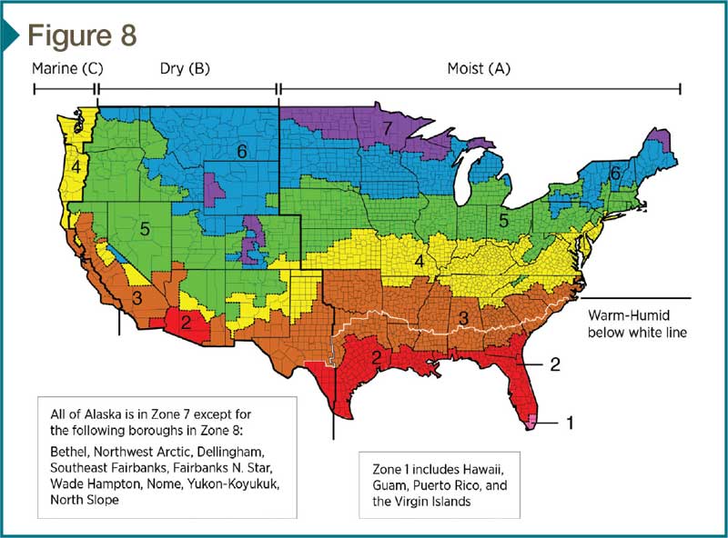
Next, determining IgCC thermal-value requirements is complicated, as several steps must be taken to arrive at the appropriate insulation R-values. Finally, proper determination of roof and wall R-values requires additional understanding of the specific type of roof and wall assembly involved, as well as the correct climate zone for the project. (Figure 8 offers a color-coded illustration of the country by zone.)
To improve understanding of these confusing and complicated prescriptive R-value requirements, the Center for Environmental Innovation in Roofing (CEIR), collaborating with PIMA, has published an easy-to-use resource for building designers. The Roof and Wall Thermal Design Guide provides a reference tool to help building designers make the best roof and wall insulation decisions for both new and existing buildings. (Click here[12] to download a free copy.) It specifically addresses the complexity of different prescriptive roof and wall thermal values in the 2012 I-Codes by providing an organized, step-by-step approach to determining the climate-appropriate R-value for a limited number of common roof or wall assemblies.
Step one: Select the climate zone
In addition to an illustrated map of the United States, the guide provides a link to detailed county-by-county climate zone information maintained by DOE’s Pacific Northwest National Laboratory (PNNL).
Step two: Select the roof or wall assembly
The guide provides prescriptive R-value information for major roof and wall assembly types referenced in the I-Codes. This includes roofs with insulation above the roof deck along with wood-framed walls and metal-framed walls.
Step three: Select the model code path
The guide provides separate R-value tables for 2012 IECC, 2012 IgCC, ASHRAE 90.1-2010, and ASHRAE 189.1-2011.
Step four: Look up the R-value
After the appropriate R-value table is located, the correct R-value may be determined by cross-referencing the relevant I-Code/ASHRAE standard with the appropriate climate zone.
Limitations of the guide
The CEIR and PIMA Roof and Wall Thermal Design Guide achieves its simplicity by narrowly focusing on one aspect of the I-Codes, while not addressing many other important requirements. The specific prescriptive thermal values for wall and roof assemblies provided by the guide are required only if the energy efficiency of the building is not determined using approved energy modeling software.
Thus, many wall and roof assemblies must incorporate structural, wind, and seismic design requirements not shown in the simple illustrations of this guide. The guide also does not cover other important thermal design requirements for roofs and walls, including use of ‘cool’ roof surfaces in the warmest climate zones or use of roof and wall vapor barriers in northern climates. In addition to a tight focus on only prescriptive R-values, the guide also concentrates strictly only on the most common types of roof and wall assemblies used in conventional commercial building design.
Another limitation of the guide is these codes and standards must be adopted by state and local jurisdictions—typically via legislative statute or a mandated code-adoption process. While some states may have adopted a version of the 2012 I-Codes, it is usually best to use the most up-to-date design information when designing a new building or renovating existing buildings. Further, each state and municipality adopting the I-Codes may include revisions or amendments to the code, which can change the prescriptive R-value requirements shown in the guide.
Some states and municipalities also may adopt only the ASHRAE version of the code as the prevailing standard. As well, the newer above-the-code standards of 2012 IgCC and ASHRAE 189.1 may be adopted by states and municipalities to apply only to certain projects, such as public facilities rather than private buildings.
The specific requirements of any individual state or municipal code jurisdiction is obviously beyond the scope of such a basic guide. However, a very useful online reference for state and local code requirements is sponsored and maintained by the non-profit Building Codes Assistance Project (BCAP). Its Online Code Environment and Advocacy Network[13] enables designers to select any state from an interactive U.S. map and discover which model code has been adopted, what amendments (if any) have been enacted, and what procedures and timetable are followed to update the code.
Conclusion
Perhaps the biggest dilemma in using the I-Code references is it is so difficult to research and obtain the actual R-values of the roof systems available in today’s marketplace. This is another limitation of using this type of process to determine actual R-values. The development of a more up-to-date and accurate guide listing the actual R-values of all the individual roof and wall assembly components would yield a better benchmark to begin the process of using the guide with measured confidence.
It may be a difficult process to understand the methods used to establish the true R-values and U-values of the different codes and standards. With hope, a neutral agency or impartial party will develop an accurate material list of all the individual components important to aid in the process of determining more accurate results. The various testing methods described in this article are in place, allowing others to help to reduce the effects of global warming, which will not happen on its own.
It is also critical to become more aware of the consequences of not following through with improving on the accuracy of the methods used to perform these calculations—which, in turn, determines the best practices in our generation’s effort to get global warming and energy consumption under control. A sufficiently well-funded agency or a group of individuals who have the technology to perform this work on a larger scale is needed. This way, in the best-case scenario, the industry can commit its advanced capabilities to slowing down the detrimental fallout of global warming and energy consumption.
Anthony Katona, CDT, is the president of Alliance Roof Consultants Inc., and has been providing professional services as a building envelope and commercial roof consultant since 1999. With construction experience spanning nearly 30 years, he has extensive experience in building envelope and commercial roof consulting, along with general contracting. Katona has served as a member of the Editorial Advisory Board of The Construction Specifier. He can be reached at alliancerc@verizon.net[14].
- [Image]: https://www.constructionspecifier.com/wp-content/uploads/2017/03/bigstock-162615353.jpg
- here: http://continuingeducation.bnpmedia.com/course.php?L=457&C=1487
- here: http://c.ymcdn.com/sites/www.polyiso.org/resource/resmgr/technical_bulletins/tb403_nov11.pdf
- National Roofing Contractors Association: http://www.nrca.net
- [Image]: https://www.constructionspecifier.com/wp-content/uploads/2017/03/Envelope-Figure-1.jpg
- [Image]: https://www.constructionspecifier.com/wp-content/uploads/2017/03/Envelope-Figure-2.jpg
- [Image]: https://www.constructionspecifier.com/wp-content/uploads/2017/03/Envelope-Figure-3.jpg
- [Image]: https://www.constructionspecifier.com/wp-content/uploads/2017/03/CS_Mar_2017_HR-32.jpg
- [Image]: https://www.constructionspecifier.com/wp-content/uploads/2017/03/Envelope-Figure-6.jpg
- [Image]: https://www.constructionspecifier.com/wp-content/uploads/2017/03/Envelope-Figure-7.jpg
- [Image]: https://www.constructionspecifier.com/wp-content/uploads/2017/03/Envelope-Figure-8.jpg
- here: http://www.roofingcenter.org
- Online Code Environment and Advocacy Network: http://energycodesocean.org/code-status-commercial
- alliancerc@verizon.net: mailto:alliancerc@verizon.net
Source URL: https://www.constructionspecifier.com/codes-and-standards-for-energy-conservation/