Complex dewatering underway at Colorado mixed-use community
Deepwell dewatering wells chosen
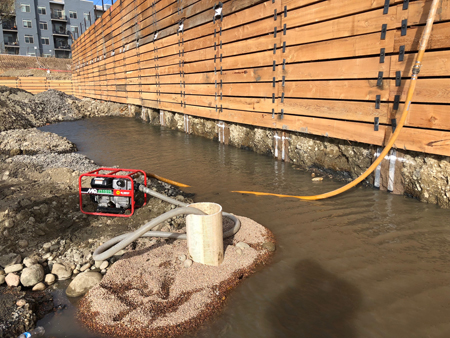
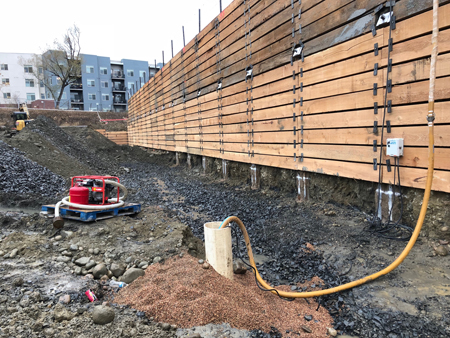
What a difference a day makes. Dewatering Reve’s south excavation utilizing filtered portable sump well installation. Before and after shots are shown above.
Photo © David Giles, TerraFirma Earth Technologies
With the excavation extending well beyond the limits of a traditional vacuum wellpoint dewatering system, and the anticipated flow rates exceeding that of an ejector-well dewatering system, the project team chose to rely on closely spaced, large diameter deepwell dewatering wells as the primary means of controlling the groundwater. The deepwell dewatering wells were installed from ground surface, just outside the excavation’s h-pile and wood lagging support system. With the perimeter of both the south and north parcel excavations exceeding 2000 lineal feet, a total of 52 deepwell dewatering wells were installed.
To install the wells, the dewatering firm utilized a hydraulic drilling rig to advance the 762-mm (30-in.) diameter borehole to the designed termination depth of 10 m (32 ft), excavating the extensive layer of sand, gravel, cobbles, and boulders. Additionally, by utilizing a powerful rig, the project team was able to penetrate nearly 3 m into the underlaying bedrock, creating a ‘sump-effect’ along the entire excavation footprint. This allowed the dewatering team to draw down the water further, closer to the bedrock/alluvial interface.
Portable sump wells supplement traditional deepwell dewatering wells
The dewatering plan also included the installation of strategically placed portable sump wells within the excavation to supplement the deepwell dewatering wells. These were necessary because of the excavation extending below the rock/alluvium interface, according to Leonard. The portable sump wells were utilized to handle perched/trapped groundwater within the excavation, as the excavation encroached on the bedrock/alluvial interface. Each portable sump can consisted of a 305-mm (12-in.) diameter x 30-m long polyvinylchloride (PVC) factory-slotted well screen. Each sump can was fitted with an electrically driven submersible dewatering pump assembly. The sump wells were drilled in from the top of bedrock, extending approximately 3 m deep. The sump well was then surrounded with a select filter material.
Leonard said, “Selecting the proper filter material and placement method was very important. By pre-filtering the groundwater prior to collecting it in the common discharge manifold and ultimately through groundwater treatment-filtration equipment installed at ground surface, additional costly treatment measures were avoided by preventing premature clogging and fouling of the treatment equipment. Each sump pump was also fitted with a liquid level control device that turned the pump on and off, based on the water level within the sump, preventing the pumps from running dry and causing premature pump failure.”
Cleaning of water prior to discharge
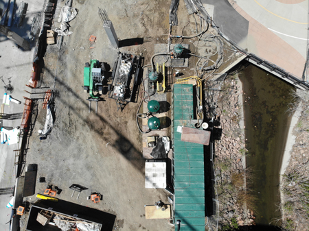
Photo © Bairn Leonard, TerraFirma Earth Technologies
From the deepwells, the groundwater was directed to Boulder’s Left Hand Ditch, directly adjacent to the site. However, as is true of many construction sites along Denver’s front range, the preliminary geotechnical and environmental sampling reports revealed contaminated groundwater.
Following the approval of the remedial discharging of the surface water permit from the Colorado Department of Public Health and Environment (CDPHE), the project team developed a remedial activities management plan to reduce the pollutants of concern to below the limits set forth in the permit.
The groundwater treatment plan included the introduction of sodium hypochlorite (NaClO) into the dewatering influent water to oxidize iron (Fe), and manganese (Mn). Caustic acid was also dripped into the tanks as a means of controlling pH, further promoting the oxidation of the metals. These reactions took place in two, 79,494-L (21,000-gal) flocculation tanks. From the flocculation tank, the water was pumped through two, 12-unit bag filtration pods to capture the flocculated metals. Granular activated carbon was added to the treatment train to remove volatile organic compounds (VOCs) and residual chlorine in the treated water.
“This process has proven effective and cost efficient in achieving the desired results. The system was designed for flows up to 1893 L (500 gal) per minute,” added Leonard added. “Once the site was dewatered, the system was resized for lower flow rates, significantly reducing the area required to accommodate the equipment on an already congested site—a benefit to this near-zero lot line project—returning pure, drinkable water to the Left Hand Ditch.”
Tony Brace, general superintendent of Colorado, Southern Land, said, “This project, like many others, was different in the field than it was on paper. For example, the discharge manifold was modified in the field as it was being laid. The dewatering team had the flexibility to work with the other trades, giving access to the people that needed it, which kept the project on time.”
 David Giles is president of TerraFirma Earth Technologies. Giles has a BS in geology from Iowa State University and 33 years of experience in developing and implementing design-build solutions for construction dewatering and groundwater control using deep wells, wellpoints, and ejector systems. He enjoys collaborating with project teams to find the approach that will yield the highest value. Giles can be reached at dgiles@tfearth.com.
Sign up for our weekly newsletter
Architectural materials and methods delivered right to your inbox
- CSI News and Notes: CSI Foundation’s construction camp; CSI spring exam; and more
- CSI News and Notes: CSI’s credentials; CSI conference theme; and more
- To be specific – CSI supports young AECO professionals
- CSI News and Notes: CSI’s foundation scholarships, national conference, and Crosswalk
- CSI News and Notes: AI’s impact; CSI 2024 conference, and more
Products


Read the Latest Issue