

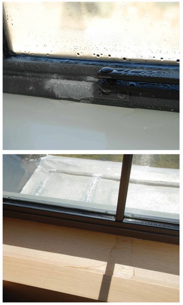
Skylights pose a unique challenge for condensation for several reasons. First, an insulating glass unit (IGU) placed at an angle will have lower performance than the same unit in vertical orientation. This is caused by increased convection within the air space of the IGU lowering the overall U-factor. Second, near-horizontal elements such as skylights tend to lose a greater amount of heat to the sky on clear evenings than vertical walls, a phenomenon known as ‘night sky radiative cooling’. Third, and the most misunderstood, ‘warm air rises’ is often cited by designers as a reason for not adding supplemental heating to skylight areas or choosing higher performance systems. However, the rate of heat gain to natural convection/rising air is almost always lower than the rate of heat loss by the skylight to the exterior. This imbalance produces lower surface temperatures on the skylight, thereby increasing the risk of condensation. The problem of heat delivery is not unique to skylights—windows and similar elements located far from heat sources (air vents, radiators, etc.) experience a similar phenomenon that can result in lower surface temperatures and increased condensation risk. Examples include tall or multistory curtain wall systems with heating at the sill level only or windows installed in deep recesses or alcoves.
Designing to avoid condensation
The first step to designing for condensation resistance in any building is to establish the interior design conditions (dewpoint) so the potential risk of condensation is clear. This will require coordination between the project team members, including the architect and mechanical engineer. Designing for condensation control in a mechanically ventilated office space (i.e. low winter dewpoint) is a simpler task than in a high-humidity space such as a museum. Understanding the interior environment and selecting appropriate systems is the key to success in these situations.
As noted above, given the potential for condensation on fenestration systems, manufacturers provide information on the relative condensation resistance of these products. Reviewing this information and specifying systems appropriate for the intended interior environment must happen early in the design. When reviewing product data, it is important to make sure the data or test report is similar enough to the intended project conditions. For example, many window and window wall systems are installed using perimeter ‘receptors’ or ‘subsills’ that can affect thermal performance, but this information may not be included in the product test report or stated characteristics. For opaque elements such as walls and roofs, the use of continuous insulation (ci)—typically mandated by modern energy codes—and the avoidance of thermal bridging through these elements are required.
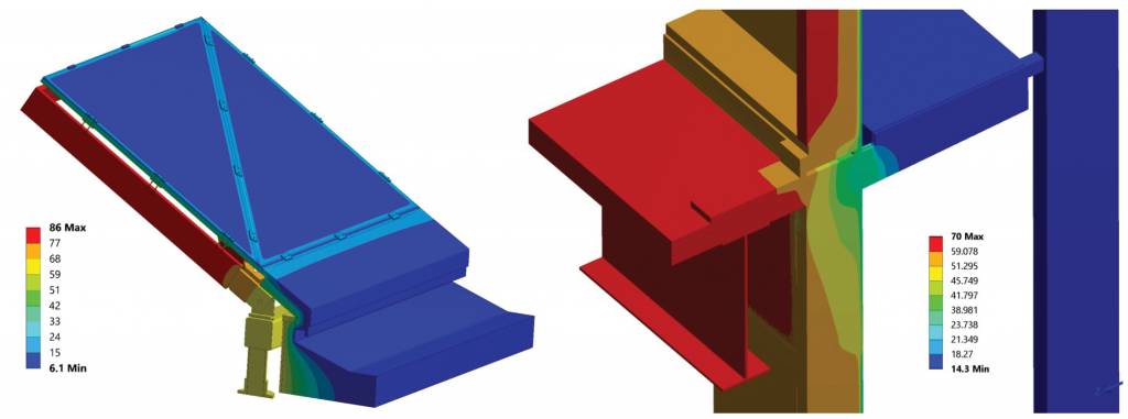
For new construction, thermal modeling is often used during the design phase as a tool to guide the project team’s decision-making regarding fenestration products and placement within the wall assembly. Modeling is necessary in these cases since the complex geometry of elements such as window clips and other attachments cannot be evaluated by inspection unlike simple elements like ci outboard of the wall framing. By modeling specific details likely to experience condensation, such as window-to-wall transitions, designers can determine the window product, glass type, surrounding materials, and placement needed to avoid condensation at the project conditions. Modeling can vary from simple, 2D thermal analysis to complex, 3D models for larger or more intricate systems like custom skylights or curtain wall systems with projecting exterior elements such a sunshades or walkways (Figure 2).
Investigating condensation
When condensation occurs, a wide range of investigative methods and tools can be used to determine the cause(s).
Data loggers, that are used to measure RH and air and surface temperatures can be installed on existing construction to record trends within an interior space and also determine if the interior conditions are a contributing factor. This is especially true for naturally ventilated spaces where calculation or prediction of conditions is difficult (as discussed above). Data loggers should be utilized during the time of the year when condensation is typically observed and must remain within the space for a few weeks, or until multiple instances of condensation occur. Comparing the information recorded by the loggers to the exterior conditions and, if noted, when condensation occurred, can help to determine the cause. For example, if the condensation happens on the interior of fenestration products in the winter during periods of cold exterior temperatures, and the data loggers measure high temperature and RH within the space where the phenomenon occurs, the mechanical systems should be reviewed and adjusted to decrease the condensation potential. If high humidity conditions only occur during periods of above-average occupancy or peak occupant loads, it is possible the mechanical systems were improperly designed.
Abnormally cold surface temperatures without elevated RH conditions will push the focus to the specific elements where condensation is occurring, as opposed to the interior conditions. Infrared (IR) thermography can be used to evaluate the temperature of interior surfaces to identify cold spots, which will likely correlate with locations where condensation was observed. Cold spots may indicate thermal bridging of assembly components and discontinuities of the envelope. They could also mean air leakage, which can cause lower localized surface temperatures and exacerbate condensation issues. The advantage of IR thermography is it can quickly allow an investigator to visualize surface temperatures on both large and small components, allowing for the observation of temperature patterns and trends that would not be apparent (or at least very difficult to discern) from spot measurements. Thermal modeling of the affected elements, using field-measured temperatures as a point of calibration, can also be useful in understanding the cause(s) of condensation, analyzing its frequency based on the exterior climate, and designing the remedial repairs.
Remediating condensation
There are multiple ways to remediate condensation. Methods used to address condensation can vary significantly, from minor adjustments to complete replacement of fenestration systems. The intensity of a repair will depend on factors such as project conditions, accessibility, budget, and the owner’s tolerance for condensation.
The least intrusive method to decrease the condensation potential is adjusting the mechanical system(s). A simple change in setpoints or adjustment of ventilation air (if used) can reduce interior moisture levels enough to produce a moderate reduction in the incidence of condensation. If conditions cannot be modified by making changes within the existing system tolerances, added equipment or ductwork may be necessary—this could be more intensive than repairs to the condensing elements themselves.


Am building home in norther Ontario, presently framing basement. Exterior walls, roof , etc are done however apart from ICF in basement upstairs not yet insulated.
Outside temperatures are now dipping well below freezing. For the next month or so am I better to have no heat at all in basement as we work or is it ok to maintain a temp just above freezing? Which will minimize condensation until we can fully insulate? Thank you.