Condensation: The misunderstood problem
by sadia_badhon | November 28, 2019 11:07 am
by Danielle A. DiDomizio and Sean M. O’Brien, PE
 [1]
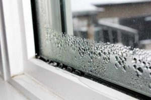
[1]Condensation has confused and frustrated the construction industry for decades. It can occur on visible surfaces or within concealed assemblies, such as wall or roof cavities, and on just about any type of building material.
The issues associated with condensation vary and, if concealed, may go unnoticed until a ‘musty’ smell leads to removal of interior finishes, and the discovery of organic growth, wood decay, and/or corroded metals. Modern fenestration products made of moisture-resistant materials such as aluminum or painted steel may not corrode or decay, but adjacent ones, such as wood trim and paper-faced gypsum wallboard, are susceptible to moisture and will continue to deteriorate if condensation is unaddressed.
Condensation causes
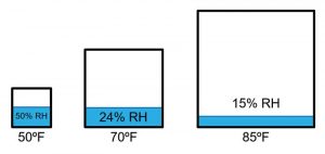
Condensation describes the phase change process by which water vapor turns into a liquid. A given volume of moist air will begin to undergo this process at a temperature known as the dewpoint. The dewpoint is a function of the absolute moisture content of the air, as opposed to relative humidity (RH), which is a result of both moisture content and temperature (i.e. warmer air can hold more moisture than colder air). Thus, a higher dewpoint equates to greater moisture levels regardless of interior temperature. Figure 1 shows this graphically. The sample of moist air at 10 C (50 F) and 50 percent RH (i.e. 50 percent saturation) has a dewpoint of 0 C (32 F). Raising the temperature of the sample increases the amount of moisture it can hold, so the RH goes down even though the dewpoint remains the same for the 21 C (70 F) and 29 C (85 F) samples. This is an important point, as many designers tend to think in terms of RH and do not at all consider the effects of temperature. The dewpoint of a set of temperature/RH conditions can be obtained easily from reference tables (psychrometric charts) or calculated using software, online tools, and mobile applications. The advantage of understanding the dewpoint of a built environment is very simple: In buildings, condensation occurs on surfaces colder than the dewpoint temperature. This provides a clear point of design guidance—susceptible surfaces must be maintained above the dewpoint to remain dry in-service.
Interior moisture sources
 [2]
[2]Images courtesy Simpson Gumpertz & Heger, Inc.
The dewpoint in a building depends on a range of factors, some of which are better understood than others. In a typical building, occupant-generated moisture is the primary source of moist air. Respiration, handwashing, and in residential buildings, showering/bathing and cooking, all increase the amount of moisture in the air. The majority of commercial spaces are mechanically ventilated with outside air. This acts to dilute interior moisture levels with drier air from the exterior during cold weather, keeping RH levels fairly low (20 to 25 percent) at code-minimum ventilation rates. The RH in residential buildings is more difficult to predict, as many of these structures (both single- and multi-family) rely on operable windows for natural ventilation, as opposed to fixed mechanical systems. Depending on the airtightness of the building enclosure, the rate of moisture dilution can vary significantly, resulting in a range of interior RH levels. Special-use buildings such as data centers, hospitals, and museums/archives will often maintain specific temperature and RH levels for various purposes, including static discharge control, patient comfort or wellness, and preservation of artwork and artifacts. Buildings housing indoor swimming pools will have a high RH (at elevated temperature) due to the use of the facility. Lastly, many previously non-humidified buildings such as offices and residential spaces are now being humidified for various reasons, including comfort, potential benefits for people with conditions such as asthma, and stability of interior finishes and furnishings. In these cases, the design dewpoint is simple to obtain by discussing interior condition setpoints for both temperature and RH with the project’s mechanical engineer.
Susceptible surfaces
Low-temperature surfaces can occur in buildings for a variety of reasons. As the elements of the building typically made from the highest conductivity materials such as steel and aluminum and have low thermal resistance relative to insulated elements such as walls and roofs, fenestration products typically have the highest potential for condensation. In recognition of this risk, industry organizations such as the American Architectural Manufacturers Association (AAMA) and the National Fenestration Rating Council (NFRC) have developed guidelines and simple rating systems (condensation resistance factor [CRF] and condensation resistance [CR] respectively) for evaluating the relative condensation resistance of these elements. The same is not true for opaque wall assemblies. They are less susceptible due to the higher insulation values and the use of materials with low conductivity. Condensation on opaque wall elements is typically caused by thermal bridging, where a high-conductivity element allows heat flow to bypass a lower-conductivity element such as thermal insulation.
Designing against thermal bridging has become more of an issue in recent years due to the increased stringency of energy codes and regulations. These standards aim to eliminate thermal bridging for the purpose of reducing heat losses/gains through the building enclosure. However, this is still a common problem due to the also-increasing complexity of buildings and demands of designers and owners. Where fenestration meets opaque walls, thermal bridging is of greater concern, as conductive materials (often needed for structural attachment of the assembly) can lead to increased heat losses and reduced overall performance from the system(s). The authors have seen cases where owners have spent extra on high-performance fenestration systems only to have the overall effect reduced to ‘typical’ levels by poor thermal detailing at the perimeters and attachments.
 [3]
[3]Skylights pose a unique challenge for condensation for several reasons. First, an insulating glass unit (IGU) placed at an angle will have lower performance than the same unit in vertical orientation. This is caused by increased convection within the air space of the IGU lowering the overall U-factor. Second, near-horizontal elements such as skylights tend to lose a greater amount of heat to the sky on clear evenings than vertical walls, a phenomenon known as ‘night sky radiative cooling’. Third, and the most misunderstood, ‘warm air rises’ is often cited by designers as a reason for not adding supplemental heating to skylight areas or choosing higher performance systems. However, the rate of heat gain to natural convection/rising air is almost always lower than the rate of heat loss by the skylight to the exterior. This imbalance produces lower surface temperatures on the skylight, thereby increasing the risk of condensation. The problem of heat delivery is not unique to skylights—windows and similar elements located far from heat sources (air vents, radiators, etc.) experience a similar phenomenon that can result in lower surface temperatures and increased condensation risk. Examples include tall or multistory curtain wall systems with heating at the sill level only or windows installed in deep recesses or alcoves.
Designing to avoid condensation
The first step to designing for condensation resistance in any building is to establish the interior design conditions (dewpoint) so the potential risk of condensation is clear. This will require coordination between the project team members, including the architect and mechanical engineer. Designing for condensation control in a mechanically ventilated office space (i.e. low winter dewpoint) is a simpler task than in a high-humidity space such as a museum. Understanding the interior environment and selecting appropriate systems is the key to success in these situations.
 [4]
[4]As noted above, given the potential for condensation on fenestration systems, manufacturers provide information on the relative condensation resistance of these products. Reviewing this information and specifying systems appropriate for the intended interior environment must happen early in the design. When reviewing product data, it is important to make sure the data or test report is similar enough to the intended project conditions. For example, many window and window wall systems are installed using perimeter ‘receptors’ or ‘subsills’ that can affect thermal performance, but this information may not be included in the product test report or stated characteristics. For opaque elements such as walls and roofs, the use of continuous insulation (ci)—typically mandated by modern energy codes—and the avoidance of thermal bridging through these elements are required.
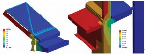
For new construction, thermal modeling is often used during the design phase as a tool to guide the project team’s decision-making regarding fenestration products and placement within the wall assembly. Modeling is necessary in these cases since the complex geometry of elements such as window clips and other attachments cannot be evaluated by inspection unlike simple elements like ci outboard of the wall framing. By modeling specific details likely to experience condensation, such as window-to-wall transitions, designers can determine the window product, glass type, surrounding materials, and placement needed to avoid condensation at the project conditions. Modeling can vary from simple, 2D thermal analysis to complex, 3D models for larger or more intricate systems like custom skylights or curtain wall systems with projecting exterior elements such a sunshades or walkways (Figure 2).
Investigating condensation
When condensation occurs, a wide range of investigative methods and tools can be used to determine the cause(s).
Data loggers, that are used to measure RH and air and surface temperatures can be installed on existing construction to record trends within an interior space and also determine if the interior conditions are a contributing factor. This is especially true for naturally ventilated spaces where calculation or prediction of conditions is difficult (as discussed above). Data loggers should be utilized during the time of the year when condensation is typically observed and must remain within the space for a few weeks, or until multiple instances of condensation occur. Comparing the information recorded by the loggers to the exterior conditions and, if noted, when condensation occurred, can help to determine the cause. For example, if the condensation happens on the interior of fenestration products in the winter during periods of cold exterior temperatures, and the data loggers measure high temperature and RH within the space where the phenomenon occurs, the mechanical systems should be reviewed and adjusted to decrease the condensation potential. If high humidity conditions only occur during periods of above-average occupancy or peak occupant loads, it is possible the mechanical systems were improperly designed.
Abnormally cold surface temperatures without elevated RH conditions will push the focus to the specific elements where condensation is occurring, as opposed to the interior conditions. Infrared (IR) thermography can be used to evaluate the temperature of interior surfaces to identify cold spots, which will likely correlate with locations where condensation was observed. Cold spots may indicate thermal bridging of assembly components and discontinuities of the envelope. They could also mean air leakage, which can cause lower localized surface temperatures and exacerbate condensation issues. The advantage of IR thermography is it can quickly allow an investigator to visualize surface temperatures on both large and small components, allowing for the observation of temperature patterns and trends that would not be apparent (or at least very difficult to discern) from spot measurements. Thermal modeling of the affected elements, using field-measured temperatures as a point of calibration, can also be useful in understanding the cause(s) of condensation, analyzing its frequency based on the exterior climate, and designing the remedial repairs.
Remediating condensation
There are multiple ways to remediate condensation. Methods used to address condensation can vary significantly, from minor adjustments to complete replacement of fenestration systems. The intensity of a repair will depend on factors such as project conditions, accessibility, budget, and the owner’s tolerance for condensation.
The least intrusive method to decrease the condensation potential is adjusting the mechanical system(s). A simple change in setpoints or adjustment of ventilation air (if used) can reduce interior moisture levels enough to produce a moderate reduction in the incidence of condensation. If conditions cannot be modified by making changes within the existing system tolerances, added equipment or ductwork may be necessary—this could be more intensive than repairs to the condensing elements themselves.
 [5]
[5]Providing supplemental heat to the fenestration in the form of warm air directed at the system can reduce, or eliminate, interior condensation by increasing local temperatures, heat delivery to the assembly via moving air, and evaporation rates of condensation that may form on the surface (again, due to moving air). Unfortunately, this approach is more appropriate for an initial design due to the difficulty of running new systems within the constraints of an existing building. Other options for supplemental heating include electric resistance heat trace and radiant heating systems. Heat trace, although effective at delivering heat directly to frame components (where it is needed the most), requires new wiring systems and periodic maintenance, although both may still be less expensive than replacing a building enclosure element. From a non-technical standpoint, however, it might be difficult to design heat trace systems capable of meeting electrical or building codes, as few products are specifically designed or certified to function in this application. Radiant heat systems may require significant input of heat to effectively warm all surfaces on the fenestration. Since radiative heat transfer requires the surfaces being heated to be ‘visible’ to the heat source, inverted or partially concealed surfaces may not receive the same level of heat as surfaces with direct line-of-sight to the heater. While similar effects may occur with warm air systems, air will tend to flow around components and can reach some (but not all) surfaces that would otherwise be ‘invisible’ to radiant heat. The space requirements for radiant panels and need for line-of-sight make radiant heating suited to very specific situations only.
If it is determined condensation occurs due to thermal bridging directly through window frame components or the surrounding assembly, replacement or in-situ modifications of these elements may be required. Given the potential cost and difficulty of this type of repair, especially in an existing building, exploring the other options discussed above should always be done as a first step.
Case studies: Too much moisture (on purpose)
 [6]
[6]As described above, it is becoming more commonplace for residential buildings, even single-family homes, to be intentionally humidified. In some cases, the decision to humidify is not made as a team, but by only one or two parties. The authors investigated a project in northeastern United States where the disconnect between design team members resulted in significant condensation and a drawn-out legal battle over damages.
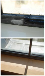
In this case, the owner requested humidification based on the amount of fine woodwork and the furniture/artwork in the house, as well as for the potential health benefits. The humidification system was designed by the mechanical engineer and clearly shown on their drawings, but not fully appreciated by the architect. The critical factor in this instance was the selection of non-thermally broken steel windows as the primary fenestration system for the building. Steel windows offer a unique, historical appearance with very narrow frame profiles, often preferred by designers to ‘bulkier’ wood or aluminum frames. However, steel is an excellent conductor of heat, resulting in low interior surface temperatures. In historic buildings, dewpoints were low due to ‘leaky’ enclosures and low interior moisture loads, allowing for these windows to be widely utilized throughout wintry climates with only minimal condensation at the coldest times of the year. In this building, low surface temperatures and high dewpoint (approximately 5 C [41 F] based on conditions of 21 C [70 F]/35 percent RH) resulted in significant condensation and finish damage in the first few winter months the building was occupied (Figure 3). At the project conditions, frame temperatures were often below freezing, resulting in ice accumulation on sills. This led to prolonged damage, as the ice would take longer to melt and dissipate than liquid water on the frame surfaces.
In this case, a simple discussion between the parties, as well as better understanding of the performance of steel windows relative to other systems, could have prevented these problems early in the design process. The authors are unaware of the results of the (ongoing) dispute, but potential remedial options would have included re-routing of ductwork to provide localized heating or, more likely given the severity of the problem, replacement of the windows with thermally efficient systems. In this case, the owner had told the authors reduction of the interior RH was not an option.
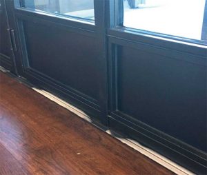
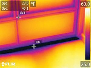
In a related case, the authors investigated a similar project several years later. In this building, a large, humidified single-family residence, the architect had specified thermally broken steel window and doors for both CR and energy efficiency. However, during the shop drawing process, they selected a non-thermally broken threshold to be used below the doors and fixed sidelights. The result of this was a primary window and door system with sufficient condensation resistance for the given interior conditions, but that experienced heavy condensation and frost on the thresholds during the winter (Figure 4). The authors performed an investigation including IR thermography and thermal analysis to evaluate the performance of the installed systems. The IR scans (Figure 5) and the measurements showed surface temperatures on the solid aluminum thresholds were up to –11 C (20 F) colder than those on the thermally broken window and door frames. Legal action had resulted in a settlement agreement, and the end-result was the installation of new, custom-fabricated (to allow for installation around mullions and other non-removable elements), thermally broken thresholds to provide similar performance to the doors and windows. A week of near-design exterior conditions provided a natural performance test for the initial mockup installation (condensation had not occurred, while other original thresholds were covered with frost) prior to the full-scale installation. This case is a good example of the importance of detailing and the use of accessory products (such as thresholds)—specifically, how these types of decisions can have very significant impacts on overall system performance if they are not fully understood.
Too much moisture (by accident)
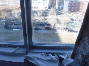
This case study involves a new residential, multifamily building in northeastern United States that experienced significant condensation on the exterior windows during its first winter of operation (Figure 6). The authors’ firm was contacted by one of the building residents and asked to “confirm that we have thermally broken windows” in the façade. The building was recently completed and occupied, and was in the midst of its first winter season when occupants began reporting condensation, often heavy to the point where water would pool on the adjacent flooring. The building was a condominium, where occupants had purchased their individual units based on an ‘offering plan’ describing the features and the performance of the structure. It was designed and built at a time when the local energy code was undergoing significant changes, both in terms of improved thermal performance and airtightness, the latter being a relatively new concept in building design for energy efficiency (as opposed to the more well-understood concepts of increased insulation and higher performing fenestration). To achieve code compliance, all exterior walls were insulated with closed-cell spray applied foam (ccSPF) insulation to provide both high R-value and airtightness, and fenestration was well-integrated with the exterior wall system using perimeter membrane flashing.
 [7]
[7]Several occupants, having performed some limited review of the offering plan and the internet (and with little background in architecture or engineering), concluded the aluminum windows and doors were not thermally broken as noted in the offering plan, and assumed they would have a strong case against the building’s developer as a result. The authors’ firm performed a review of the available project documents (both architectural and mechanical drawings) as well as the offering plan, followed by an initial review of the building. Data logging devices were installed to record temperature and RH conditions within several units (almost all units at the building had reported some condensation) as well the ambient exterior conditions.
A review of the basic design parameters for the building showed the building enclosure and mechanical systems were in accordance with the relevant code requirements. A review of the window shop drawings combined with observations in the field confirmed the installed windows were thermally broken, with performance exceeding the code minimums for both U-factor and solar heat gain coefficient (SHGC). Based on these initial findings, combined with spot-measurements of high RH in several units, the investigators focused on the performance of the installed mechanical systems.
The mechanical system design utilized the ‘corridor ventilation’ strategy. This approach is primarily used due to its low installation cost since ductwork is only required for the corridors, not to each individual unit. Fresh air for the individual units is provided to the common corridors, where it is assumed to flow into the units at undercuts in the entry doors (driven by a pressure differential in the units that was created by exhaust fans). As opposed to a more controlled approach delivering a set quantity of air directly to the units (but requires more equipment and ductwork, or more façade openings), corridor ventilation cannot guarantee enough air reaches each unit, being subject to imbalances in exhaust flows between units as well as conditions at the unit entry doors, both of which are not directly addressed in the mechanical or building code. The two major impediments to the functioning of this strategy in the subject building were a lack of undercut on the entry door (which was sealed with a sweep gasket) and the use of intermittent bathroom exhaust, that was controlled by a switch and occupancy sensor in each bathroom. This meant fresh air from the corridor had a reduced pathway and intermittent driving force to enter each unit, thereby resulting in poor ventilation/air exchange within units.
 [8]
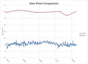
[8]The combination of an airtight exterior enclosure and inadequate ventilation resulted in extremely high RH within the space at a time (winter) when a typical mechanically ventilated building would be the driest. The authors had compared the measured interior dewpoint to exterior weather data for the project location. Comparing interior measurements to the exterior environment (Figure 7), the authors found interior dewpoints were high, far in excess of the exterior, with interior RH levels well over 60 percent. In a mechanically ventilated building, these same conditions would closely match or at least follow the same general trend. The disparity between interior and exterior conditions is indicative of occupant-generated moisture (cooking, showering, respiration, etc.) building up in the interior space, whereas it would be quickly removed/diluted with outside air in a properly ventilated space. A test of this hypothesis was performed by simply opening a window—within 10 minutes, the interior RH level had dropped by approximately 15 percent.
In evaluating potential remedial options, it was discovered the local fire code limited the size of the undercuts at unit entry doors. The reason for this was the entry doors to the units required a certain fire rating in conjunction with limiting the passage of smoke. In similar projects, this requirement often precludes the use of corridor ventilation as a viable strategy. This left the building occupants with a difficult situation—legal action against the developer would be difficult since ‘on paper’ both the architect and the mechanical engineer met the basic standard-of-care requirements in the respective codes. Options presented included localized ventilation (window trickle vents or dedicated through-wall heat recovery ventilators), new supply air ductwork between the corridors and the units, and the introduction of constant-run exhaust fans for the bathrooms to promote more airflow into the units. Larger undercuts at the entry doors were not an option given the fire code requirements, which could not be overcome without adding features to the fire alarm and mechanical systems. All options would require moderate-to-significant expense and, in some cases, modification of the exterior appearance of the building. Unfortunately, as is often the case with these projects, the authors developed multiple technically viable solutions, but given the complexities of the building and ownership, as well as the high cost of remedial repairs, the problems remained unresolved at the time of writing this article.
Conclusion
While condensation is by no means a new problem, many aspects of the design and construction of modern buildings, as well as people’s general expectations, have brought the issue to the forefront in recent years. Design professionals must be careful to understand the interior environment, select building enclosure systems with the appropriate thermal performance, and integrate them into the facility in a manner to reduce or eliminate thermal bridging. While it is possible to identify and remediate these issues, as the case studies above show these ‘fixes’ can be expensive and often involve legal action. In almost all cases, these efforts will cost more and take more time than properly designing the systems at the outset.
- [Image]: https://www.constructionspecifier.com/wp-content/uploads/2019/11/bigstock-201932266.jpg
- [Image]: https://www.constructionspecifier.com/wp-content/uploads/2019/11/Figure-1_Fenestration.jpg
- [Image]: https://www.constructionspecifier.com/wp-content/uploads/2019/11/figure-pg38.jpg
- [Image]: https://www.constructionspecifier.com/wp-content/uploads/2019/11/figure-pg40.jpg
- [Image]: https://www.constructionspecifier.com/wp-content/uploads/2019/11/Figure-6_Fenestration.jpg
- [Image]: https://www.constructionspecifier.com/wp-content/uploads/2019/11/Figure-7_Fenestration.jpg
- [Image]: https://www.constructionspecifier.com/wp-content/uploads/2019/11/Figure-8_Fenestration.jpg
- [Image]: https://www.constructionspecifier.com/wp-content/uploads/2019/11/Figure-9_Fenestration.jpg
- dadidomizio@sgh.com: mailto:dadidomizio@sgh.com
- smobrien@sgh.com: mailto:smobrien@sgh.com
Source URL: https://www.constructionspecifier.com/condensation-the-misunderstood-problem/