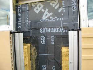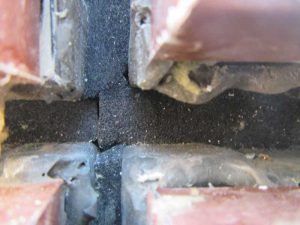
However, with this method of wall design and construction, the exterior wall performance is heavily dependent on the panel joint performance. Therefore, the joint construction should be verified through QC testing and field inspection (when access is available) and testing. Preconstruction mockup panels can be tested in the laboratory or contractor’s shop before the design is finalized to go to production (Figure 1, page 20). The mockup should include horizontal and vertical panel-to-panel joints, each unique fenestration system, and transitions to other enclosure systems (e.g. roofing, base of wall, etc.). In addition to the typical ASTM air leakage and water penetration tests, the authors recommend specifying field nozzle testing of the joint in general accordance with the American Architectural Manufacturers Association (AAMA) 501.2, Quality Assurance and Diagnostic Water Leakage Field Check of Installed Storefronts, Curtain Walls, and Sloped Glazing Systems, with a modified pressure for field checks of panel joints. While the tests described above are typically for windows and doors, the same principles can be applied to check for continuity of the main joint details between panels, and for the whole assembly in general. The authors recommend the designer specify field testing during panel erection if the project allows.
Panel joint design options

The joints between panels are the most vulnerable detail in prefabricated construction. A successful exterior building enclosure system incorporates a water barrier with flashing to contain and drain bulk water, an air barrier to minimize airflow, and a vapor retarder (where required) to manage vapor diffusion of warm, moist air onto cooler surfaces. These barriers should be continuous at joints to optimize performance and designed to accommodate the expected movement in the base building structure and between the panels. The panel joints should be designed to be weathertight using durable materials with consideration to expected service life, as repair or replacement of these materials may require removal of overlying cladding or the entire panel.
The insulation is often discontinuous at the joints and the panel perimeter has a metal extrusion to capture all four sides, thereby creating a thermal bridge. The thermal bridging decreases the façade’s overall thermal performance and provides a risk for condensation at the panel joints. The extent of the thermal impact on the overall wall performance depends on the joint detailing and the panel size. In certain applications, a thermal break could be installed within or between metal extrusions, or insulation can be included in the joint. Also, the larger the panel, the less impact the perimeter frame has on the overall thermal performance. It is important to model the panels with the edge conditions and joints in mind in order to evaluate overall thermal performance so as to show the exterior wall system indeed meets the code-required U-factor and will not cause interior surface condensation.
The following are some of the more common materials employed in panelized enclosure joint construction along with their respective advantages and disadvantages.
Sealant joints
Single-stage sealant joints alone should not be considered, as sealants are not a reliable long-term water-resistive barrier (WRB) because they are maintenance-intensive. Multiple-stage (i.e. dual-stage) sealant joints are a common choice for joint construction, as they are simple to install, cost-effective, and provide redundancy that improves the reliability of the single line of sealant (Figure 2, page 20). This joint construction relies on the rear sealant joint of the dual seal being 100 percent continuous, integrated, and well-adhered to the adjacent water/air/vapor-resistive barrier surfaces. The interior sealant joint should be drained to the exterior at panel joints on floor lines. If the cladding outboard of the interior sealant joint is deeper than a few inches, it will be extremely difficult, nearly impossible, to replace the sealant joint as it cannot be properly accessed for cleaning and prep work. It is important that the interior sealant joint be fully cured and inspected prior to the exterior sealant joint installation.


