Considerations and challenges for prefabricated wall panel enclosures
by sadia_badhon | December 21, 2020 9:46 am
 [1]
[1]by Annemarie R. DerAnanian, PE, and Mary K. Donlon, PE
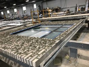
Prefabricated wall panels are individually manufactured in an offsite fabrication shop, complete with exterior cladding and fenestration, anchor system, water/air/vapor barrier(s) and flashing, insulation, and the structural framing. They are then lifted and installed onsite. These panels have the potential to accelerate the building enclosure construction schedules, provide better quality control of the wall components, and reduce construction costs. However, the advantages of using prefabricated walls can quickly diminish if not used on the ideal type of building and without careful detailing of the panel joints and proper planning between trades.
Building and site considerations
Large buildings with a uniform or repetitive façade are better suited for panelization than a more complex one with lots of transitions, as the cost benefits of the system can only be realized if the sizes and shapes can be standardized into a few types of panels that can be installed throughout the building.
 [2]
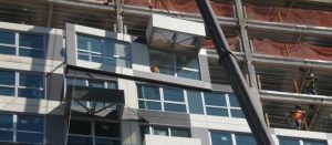
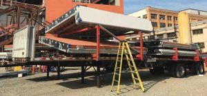
[2]Prefabricated panelized wall systems can accommodate construction sites with limited laydown space and site clearances. With traditional, site-assembled building enclosure systems, all the project materials and tools need to be stored onsite and the construction debris must be cleaned and disposed of in large dumpsters. With panelized wall systems, all the materials, tools, and large dumpsters are at the fabrication shop. The completed panels can be stored at the facility and shipped to the project site on an as-needed basis where it can be installed directly from the truck to the building, which reduces storage and construction space requirements.
Lastly, panelized wall systems may not require exterior wall access via staging or multiple aerial lifts if the joint construction is designed accordingly. Enclosure panels can be installed with a crane with minimal interior labor to guide the panels into place.
 [3]
[3]Project schedule and cost impacts
When using prefabricated panels, one should assume a longer design and preconstruction phase. Prefabricated wall panels are proprietary to the manufacturer, and the contractor is retained earlier in the project in a design-assist role. Ideally, this occurs after the schematic design phase, but prior to design development. The panel design, joint layout, typical joint geometry between adjacent panels, and panel connection to the base building structure are dictated by the contractor with input from the design team. The panel integration with adjacent systems needs to be coordinated with the architect since they will maintain authority over the entire design as the designer of record. The building owner should expect greater upfront engineering costs in the design and preconstruction phases if a panelized enclosure system is selected, as the iterations of panel shop drawings are completed in this phase instead of the construction stage.
 [4]
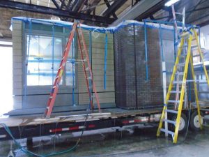
[4]Conversely, a significant benefit of prefabricated wall panels is an accelerated onsite construction schedule. The installation of exterior enclosure materials, such as waterproofing, sealants, or mortar, is limited by weather restrictions, often requiring temperatures above 4 C (40 F) without wet or humid conditions. Prefabricated panelized wall systems can allow for a year-round construction season, thus limiting lost workdays due to weather. The wall panels can be assembled in the shop at the same time as the building structure is being constructed. The duration of the exterior panel installation can be drastically shortened. As an example, a traditionally built façade system with metal panel cladding can take up to eight months to complete, from studs to cladding, but, in the authors’ experiences, the prefabricated panels can be lifted and installed in just two months, thus resulting in a net six-month gain in the overall construction schedule.
The reduction in construction schedule can be added to the benefits of year-round construction, which could result in lowering project cost.
Aesthetics
The exterior wall cladding with prefabricated wall panels can vary, though they typically incorporate a lightweight rainscreen cladding such as metal panels, terra cotta, thin-brick, and/or glass fiber reinforced concrete (GFRC) panels.
 [5]
[5]Overall panel dimensions are limited due to travel size restrictions, such as bridge clearance or width of roads or tollbooths, and the maximum panel width will vary. As a result, the panel sizes and joint spacing may not be aesthetically desirable. The joint spacing may be more obvious with some cladding types such as brick masonry, and less apparent with rainscreen metal panels, as they tend to hide the joints. Further, the panel joints are larger than a traditional one. Most construction joints are sized for building deflection, long-term creep, thermal movement, etc., but prefabricated panels require a larger joint size to accommodate construction tolerances.
Structural design
The manufacturer will need to design the panels for gravity, lateral, and hoisting loads, their attachment back to the base building structure, as well as the joint size to accommodate the anticipated movement. The panels will be attached to the structural steel or floor slab edges of the building. The panel loads and anchor locations must be provided to the structural engineer of record designing the base building structure to ensure it can support the panels and associated loads—another reason for the panels to be designed early in the design phase.
Workmanship and quality control
A benefit of the panelized wall systems is the improved quality control (QC) when constructing panels in the shop. The window penetrations, which are often the cause of exterior wall leakage in conventional construction, are installed in a controlled setting, and the installation can be regulated so the same crew installs all windows and flashing, thus leading to better and more consistent installation. Panel construction is inspected by a designated QC manager as the components of the façade are installed, and a good QC program tracks individual panels with progress sheets to confirm each step in the installation. Also, it is easy for an outside third party, such as the architect or a building enclosure consultant, to review multiple panels in a short period of time by visiting the shop without needing special access. Third-party inspections are more effective because the inspector can review conditions up close, as compared to the limited site inspections from the ground.
 [6]
[6]However, with this method of wall design and construction, the exterior wall performance is heavily dependent on the panel joint performance. Therefore, the joint construction should be verified through QC testing and field inspection (when access is available) and testing. Preconstruction mockup panels can be tested in the laboratory or contractor’s shop before the design is finalized to go to production (Figure 1, page 20). The mockup should include horizontal and vertical panel-to-panel joints, each unique fenestration system, and transitions to other enclosure systems (e.g. roofing, base of wall, etc.). In addition to the typical ASTM air leakage and water penetration tests, the authors recommend specifying field nozzle testing of the joint in general accordance with the American Architectural Manufacturers Association (AAMA) 501.2, Quality Assurance and Diagnostic Water Leakage Field Check of Installed Storefronts, Curtain Walls, and Sloped Glazing Systems, with a modified pressure for field checks of panel joints. While the tests described above are typically for windows and doors, the same principles can be applied to check for continuity of the main joint details between panels, and for the whole assembly in general. The authors recommend the designer specify field testing during panel erection if the project allows.
Panel joint design options
 [7]
[7]The joints between panels are the most vulnerable detail in prefabricated construction. A successful exterior building enclosure system incorporates a water barrier with flashing to contain and drain bulk water, an air barrier to minimize airflow, and a vapor retarder (where required) to manage vapor diffusion of warm, moist air onto cooler surfaces. These barriers should be continuous at joints to optimize performance and designed to accommodate the expected movement in the base building structure and between the panels. The panel joints should be designed to be weathertight using durable materials with consideration to expected service life, as repair or replacement of these materials may require removal of overlying cladding or the entire panel.
The insulation is often discontinuous at the joints and the panel perimeter has a metal extrusion to capture all four sides, thereby creating a thermal bridge. The thermal bridging decreases the façade’s overall thermal performance and provides a risk for condensation at the panel joints. The extent of the thermal impact on the overall wall performance depends on the joint detailing and the panel size. In certain applications, a thermal break could be installed within or between metal extrusions, or insulation can be included in the joint. Also, the larger the panel, the less impact the perimeter frame has on the overall thermal performance. It is important to model the panels with the edge conditions and joints in mind in order to evaluate overall thermal performance so as to show the exterior wall system indeed meets the code-required U-factor and will not cause interior surface condensation.
The following are some of the more common materials employed in panelized enclosure joint construction along with their respective advantages and disadvantages.
Sealant joints
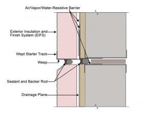
Single-stage sealant joints alone should not be considered, as sealants are not a reliable long-term water-resistive barrier (WRB) because they are maintenance-intensive. Multiple-stage (i.e. dual-stage) sealant joints are a common choice for joint construction, as they are simple to install, cost-effective, and provide redundancy that improves the reliability of the single line of sealant (Figure 2, page 20). This joint construction relies on the rear sealant joint of the dual seal being 100 percent continuous, integrated, and well-adhered to the adjacent water/air/vapor-resistive barrier surfaces. The interior sealant joint should be drained to the exterior at panel joints on floor lines. If the cladding outboard of the interior sealant joint is deeper than a few inches, it will be extremely difficult, nearly impossible, to replace the sealant joint as it cannot be properly accessed for cleaning and prep work. It is important that the interior sealant joint be fully cured and inspected prior to the exterior sealant joint installation.
 [8]
[8]Membrane
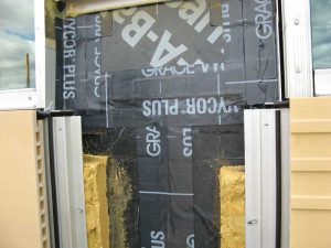
Continuous membrane, such as self-adhered or silicone membrane with bellows, provides a more reliable and durable water and air barrier in the long-term and overcomes many limitations inherent with field-applied sealant joints (Figure 3). The membrane, when properly adhered and sealed to both panels, provides continuity of the water/air/vapor-resistive barrier with the same durability and life-expectancy as the field of the wall. Membrane joints require access to the panel sheathing or membrane after the latter is installed on the building. The exterior cladding and insulation adjacent to joints must be left off the walls until after the membrane transition is installed in the field, thus increasing the installation time. As such, this joint detailing may not be feasible for all types of exterior wall claddings or aesthetic designs.
Expandable foam tapes
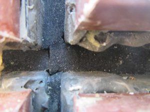
Expandable foam tapes are a time-efficient way to detail the joints between prefabricated panels during panel erection, as the tape is adhered to the panel edges before the adjacent one is installed. Once the adjacent panels are installed, the foam tape can be released to slowly expand to fill the joint and form a compression seal (Figure 4). As it expands, force is exerted onto the panel return edges, which must be solid, continuous without abrupt plane changes, and parallel.
 [9]
[9]Some foam tape manufacturer installation instructions neither require the sealing of tape edges to the panels nor sealing the butt joints at the ends of the tape with sealant, so the additional requirements to seal all edges and joints between tape rolls should be clearly specified. This is particularly important at the panel corners, as the foam tape cannot bend 90 degrees and instead must be cut, providing another vulnerability at a critical transition. The installation of the foam tape is installer dependent and it is beneficial to inspect 100 percent of the foam tape for gaps, foam defects, or unsealed cut edges if the tape is the primary WRB.
Rubber gaskets and interlocking joints
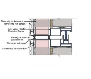
Rubber gaskets offer another time-efficient way to provide water/air/vapor-resistive barrier continuity at panel joints (Figure 5). Gaskets are applied to panels in the shop and provide a weathertight enclosure as the panel is installed. Rubber gaskets rely on the compression of the gasket against an adjacent hard substrate or another gasket to fill the joint and typically require the panel perimeters to be constructed with a metal extrusion to which the gaskets are attached. It can be challenging to achieve continuity of rubber gaskets at the four-way panel joint intersections, which has four separate gaskets with 90-degree corners coming together. Even with perfect compression and alignment of panels, a small gap remains between the gaskets. The gap requires sealing to ensure a continuous water/air/vapor-resistive barrier at the gasket intersection. Gaskets can become hard and brittle in the long run, making them less effective as the panels continue to move and deflect. Further, it is impractical to replace the gasket without deconstructing the panels.
 [10]
[10]Panel joints that use continuous interlocking male-female extrusions with gaskets, constructed similar to unitized curtain walls, can provide improved reliability and durability at the joints beyond the gasketed seals because the extrusions can be weathertight and drained. However, these wall panels are more expensive than the ones with basic metal frames.
Building transitions
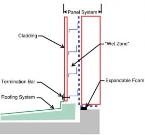
Coordination between the prefabricated panels and adjacent building enclosure systems is critical to the building’s success. In the preconstruction phase, it is imperative the project architect and subcontractors responsible for the building enclosure—panelized wall system contractor and installer, roofer, and below-grade waterproofing and window or curtain wall contractor—coordinate their shop drawings. The transitions between adjacent building components are often where maintaining the water/air/vapor-resistive water barrier continuity is the most challenging. Since panelized wall systems are proprietary and not specifically designed to integrate with other systems, more coordination between trades and construction shop drawings is needed where the panels must connect to other building components unlike conventional building construction (Figure 6).
 [11]
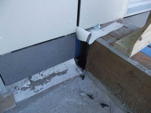
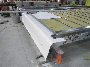
[11]A preconstruction coordination meeting with all involved contractors can alleviate much of the challenges surrounding transitions. All of the transitions to different enclosure systems should be identified and properly addressed prior to the completion of panel shop drawings and coordinated with involved trades. With proper planning, transitions can be detailed to minimize the removal or installation of the panel cladding in the field for integration. For example, the transition to a roofing system can be detailed with an oversized sheet of roofing membrane terminated in the panel behind the cladding at the shop so the roofer can attach the main roofing system to the panelized building (Figure 7). Without proper coordination, subcontractors installing adjacent systems, like roofing, do not understand how the panels are designed, often resulting in discontinuous transitions. As shown in Figure 8, this can result in significant issues like water within the panels draining directly below the roof. Having a coordination meeting that highlights the areas of concern can help avoid gaps in the four enclosure barriers, lack of clear responsibility among the trades, and compatibility issues between dissimilar materials.
Conclusion
The prefabricated panelized wall system can be field installed faster than a conventional wall system but comes with the challenge of more design and construction-team coordination and many linear feet of panel joints that can
be vulnerable to performance issues. Panelized wall systems require compromise and balance between expediency in construction and the reliability of the wall system.
The owner and designer should be aware of the risks, benefits, and limitations of panelized wall systems to decide if it is best suited to meet the project goals and provide an acceptable level of performance and longevity.
![]() [12]Annemarie R. DerAnanian, PE, is a senior project manager with Simpson Gumpertz & Heger, Inc., in Waltham, Massachusetts. As a member of the Building Technology Group, she works on projects involving waterproofing investigation and design of building envelope systems, including plazas, wall systems, windows, and roofing. She has extensive experience with both historic multi-wythe masonry and contemporary masonry veneer wall systems. DerAnanian can be reached at arderananian@sgh.com[13].
[12]Annemarie R. DerAnanian, PE, is a senior project manager with Simpson Gumpertz & Heger, Inc., in Waltham, Massachusetts. As a member of the Building Technology Group, she works on projects involving waterproofing investigation and design of building envelope systems, including plazas, wall systems, windows, and roofing. She has extensive experience with both historic multi-wythe masonry and contemporary masonry veneer wall systems. DerAnanian can be reached at arderananian@sgh.com[13].
![]() [14]Mary K. Donlon, PE, is a consulting engineer with Simpson Gumpertz & Heger, Inc., in Waltham, Massachusetts. As part of the Building Technology group, she works on variety of projects involving investigation, design, and construction administration for existing building repair projects as well as building enclosure consulting on new construction. Donlon can be reached at mkdonlon@sgh.com[15].
[14]Mary K. Donlon, PE, is a consulting engineer with Simpson Gumpertz & Heger, Inc., in Waltham, Massachusetts. As part of the Building Technology group, she works on variety of projects involving investigation, design, and construction administration for existing building repair projects as well as building enclosure consulting on new construction. Donlon can be reached at mkdonlon@sgh.com[15].
- [Image]: https://www.constructionspecifier.com/wp-content/uploads/2020/12/Picture-3.jpg
- [Image]: https://www.constructionspecifier.com/wp-content/uploads/2020/12/Picture1.jpg
- [Image]: https://www.constructionspecifier.com/wp-content/uploads/2020/12/Picture-2.jpg
- [Image]: https://www.constructionspecifier.com/wp-content/uploads/2020/12/Figure-1.jpg
- [Image]: https://www.constructionspecifier.com/wp-content/uploads/2020/12/Figure-2.jpg
- [Image]: https://www.constructionspecifier.com/wp-content/uploads/2020/12/Figure-3.jpg
- [Image]: https://www.constructionspecifier.com/wp-content/uploads/2020/12/Figure-4.jpg
- [Image]: https://www.constructionspecifier.com/wp-content/uploads/2020/12/Figure-5.jpg
- [Image]: https://www.constructionspecifier.com/wp-content/uploads/2020/12/Figure-6-alternate.jpg
- [Image]: https://www.constructionspecifier.com/wp-content/uploads/2020/12/Figure-7.jpg
- [Image]: https://www.constructionspecifier.com/wp-content/uploads/2020/12/Figure-8.jpg
- [Image]: https://www.constructionspecifier.com/wp-content/uploads/2020/12/DerAnanian.jpg
- arderananian@sgh.com: http://arderananian@sgh.com
- [Image]: https://www.constructionspecifier.com/wp-content/uploads/2020/12/Donlon.jpg
- mkdonlon@sgh.com: http://mkdonlon@sgh.com
Source URL: https://www.constructionspecifier.com/considerations-and-challenges-for-prefabricated-wall-panel-enclosures/