Construction Dewatering: Understanding its effect on below-grade waterproofing
by Katie Daniel | July 29, 2016 9:30 am

by Daniel G. Gibbons, PE, and Payal R. Vora, LEED AP
Construction site dewatering is used to locally control and lower groundwater levels in the vicinity of the excavation. This is typically done to maintain soil conditions needed during, and occasionally after, construction—for example, to keep soil dry enough for construction loads, installing building materials, or safe working conditions. Dewatering requirements for structural needs differ from those for below-grade waterproofing of the building. This article defines and describes ‘site dewatering’ during construction from the perspective of below-grade waterproofing design and installation, and highlights the differences in dewatering requirements between structural and waterproofing needs.
For below-grade construction, an adequately dry project site is an important prerequisite for providing a well-constructed below-grade waterproofing system and, ultimately, a dry interior space. This often requires water sources to be controlled with a properly designed dewatering system. To understand construction dewatering and how it can affect below-grade waterproofing, it is important to consider both the theoretical and practical aspects of how below-grade water can enter an excavation.
At a basic level, a site that includes a below-grade interior space needs to be dry enough to allow the waterproofing system to be installed, covered, and stabilized without being damaged by water. For the waterproofing system, the specific period in question extends from the completed substrate preparation for the below-grade waterproofing through to when the structural engineer notifies the contractor the construction dewatering can be turned off.
From a structural perspective, construction dewatering is required to provide an open and stable space to construct a building and prevent buoyant forces from lifting the structure until sufficient dead load is in place. (In addition to dead load, structural engineers may also use structural tie-down elements to resist buoyant forces). Although dewatering impacts both structural stability and waterproofing, the requirements for each differ. In practical terms, although lowering the groundwater level may satisfy a project’s structural requirements, the presence of standing water—or even isolated pockets of water in the excavation—can adversely impact the installation of the below-grade waterproofing and the reliability of its future performance.
In other words, the dewatering requirements for waterproofing are more stringent than the structural requirements of dewatering. Additionally, fine-tuning the system to achieve adequately dry waterproofing conditions is essential to the performance of the below-grade waterproofing and relative success of the project.
Theoretical basis dewatering
The modern understanding for how water flows through permeable soils was developed in the 19th century by Henri Darcy. (For more information, see Chapter 3 of Groundwater Lowering in Construction—A Practical Guide to Dewatering, by Pat Cashman and Martin Preene). Known as Darcy’s Law, it is expressed as:
Q = k·i·A
In this equation, ‘Q’ equals the groundwater flow rate, ‘k’ equals soil permeability, ‘A’ equals the cross sectional area through which the water flows, and ‘i’ equals the hydraulic gradient, expressed as:
dh/l
Here ‘dh’ equals the difference in total hydraulic head between the upstream and downstream ends of the flow path, and ‘l’ equals length of the flow path through the porous soils which the water flows.
The variables in Darcy’s Law help explain what groundwater flow is based on. Granular soils like gravel and sand have a higher permeability than silts and clays, and will result in higher groundwater flow, all other things being equal. Similarly, the higher the difference between the groundwater elevation at a project site and the elevation where water is being pumped out as part of the dewatering system, the higher the groundwater flow rate into the excavation.
Types of dewatering
Dewatering can be either temporary or permanent. In temporary dewatering or construction dewatering, the water table is drawn down and maintained below a certain level, which is commonly determined by the project’s geotechnical engineer to be 0.9 m (3 ft) below the bottom of the excavation. The primary objective of temporary dewatering is to remove water from the site during construction activities; after which, dewatering is stopped and the original water table is restored.
Permanent dewatering, which is achieved with exclusion, pumps, or subsurface drainage, is for the life of the structure. The objective behind permanent dewatering is to maintain a water table below a certain level—primarily to reduce buoyant forces, and also secondarily to reduce the potential for leakage into below-grade areas of the building.
Site dewatering is usually achieved by controlling groundwater through exclusion (permanent) or removing it by pumping (temporary or permanent). Groundwater control by exclusion is achieved by constructing an impermeable or low permeability cut-off wall to keep the groundwater out of the excavation. Incidental water—such as rainwater, seepage, or groundwater trapped within the cut-off area—is removed by pumping. Groundwater control by pumping is achieved by allowing groundwater into the excavation and pumping it out through sumps, or by removing it through wells or well points inside the excavation or at the perimeter. Although both methods of groundwater control are effective, groundwater control by exclusion has a lower impact on groundwater levels outside the cut-off area and is often used in areas sensitive to change in groundwater levels or where there are limitations on pumping discharge.
If the water table is lowered outside the excavated portion of a project, this can result in significant settlement of compressible soil layers outside the project—especially in normally consolidated or slightly over consolidated soils, which can significantly impact adjacent utilities, roadways, and structures. (See section 3.11 of Guidelines of Engineering Practice For Braced and Tied-Back Excavations, published by ASCE in 1997).Timber piles can rapidly decay as a result of lowered groundwater. For this reason, city building authorities typically require dewatering to occur inside the footprint of the excavation and for the shoring walls to be exposed to greater direct hydrostatic pressure, creating a higher potential for the shoring wall to exhibit leakage and to require repairs as part of the preparation of the waterproofing substrate.
Excavation and shoring leakage
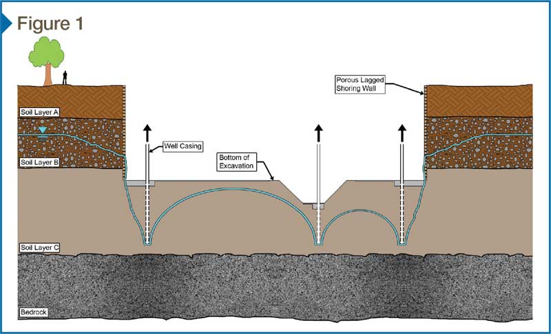
For most projects, construction dewatering drives the selection of the shoring system. Shoring systems vary in their permeability and how much groundwater they retain. The highly porous soldier beams and wood lagging shoring system (Figure 1) are on one end of the spectrum, where vertical soldier beams provide lateral stabilization to horizontally-oriented sawn lumber (i.e. lagging) inserted behind the front or back flange of the soldier beam.
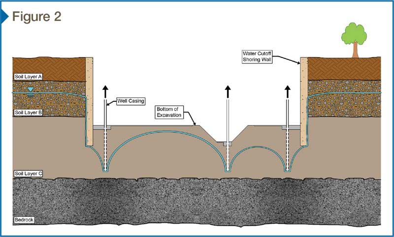
On the other side of the spectrum, there are ‘water-cutoff’ shoring systems (Figure 2), such as soil-cement mix (CSM) secant pile walls, slurry walls, and sheetpile walls—all of which may be laterally strengthened with tiebacks or lateral bracing.
CSM secant pile walls
Soil-cement mix secant pile walls are built by a hollow augur injecting a mixture of native soil, cement, water, and bentonite or polymer into the unexcavated site in rows of deep overlapping cylinders prior to excavation (typically 2757 to 6894 kPa [400 to 1000 psi] compressive strength), with every other adjacent cylinder having a soldier beam inserted for lateral stabilization. At the time of excavation, the shoring walls are scraped back to approximately the plane of the inside flange of the soldier beam before the waterproofing substrate is prepared.
From a shoring engineering point of view, this type of shoring wall is considered a ‘water cut-off’ wall. Nevertheless, from a waterproofing substrate standpoint, there is commonly a need for leakage repair to prepare the waterproofing substrate. This preparation is most extensive at tiebacks to the soldier beams, cracks in the CSM material (especially at reentrant corner conditions), and steel to CSM material interfaces.
Slurry walls
Slurry walls are reinforced concrete walls formed in soil prior to excavation; once placed, they are excavated similar to CSM secant pile walls. They are constructed by excavating a deep trench segment—commonly 1.8 to 2.4 m (6 to 8 ft) long—at the perimeter of the building, supporting the trench walls with bentonite slurry, placing reinforcement into the slurry, and then placing tremie concrete into the excavation to displace the bentonite slurry. Each wall segment constructed in this sequence overlaps in an ‘overbite’ into the next adjacent segment to form a continuous wall. From a shoring and structural engineering perspective, this type of shored wall is often used both for shoring purposes and also as the final below-grade structural wall for the project. This type of wall is normally not associated with a conventional below-grade waterproofing system, especially at ‘overbite’ locations in the wall where leakage is often pronounced. Moreover, at the base of slurry wall to cast-in-place concrete slab conditions, a trench in the slab is normally necessary to collect water that leaks through the wall and wall-to-slab interface. This results in more of a below-grade ‘water management’ system than a waterproofing one.
Sheetpile walls
Sheetpile walls are formed by driving corrugated sheets of steel into the ground, where each adjacent sheet interlocks with the next and the locations of interlock are sealed. This type of shoring wall is common in marine applications. From a waterproofing substrate standpoint, a seal is required at the interlock to prepare the substrate.
Practical perspectives and observations
The efficient water management during the dewatering process is imperative to successful waterproofing installation. To better manage water, one must first recognize the possible sources of water that can enter an excavated site. These potential sources include:
- precipitation (rain and snow);
- site water (including sources such as surface runoff and from construction activities);
- groundwater; and
- perched water (water held on an impervious soil/rock layer above the water table).
On the other side of the equation, it is important to consider the ways water leaves the site, which include:
- evaporation; and
- well casings with pumps.
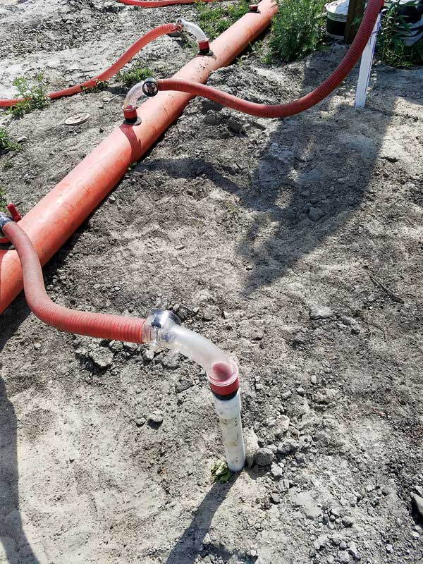
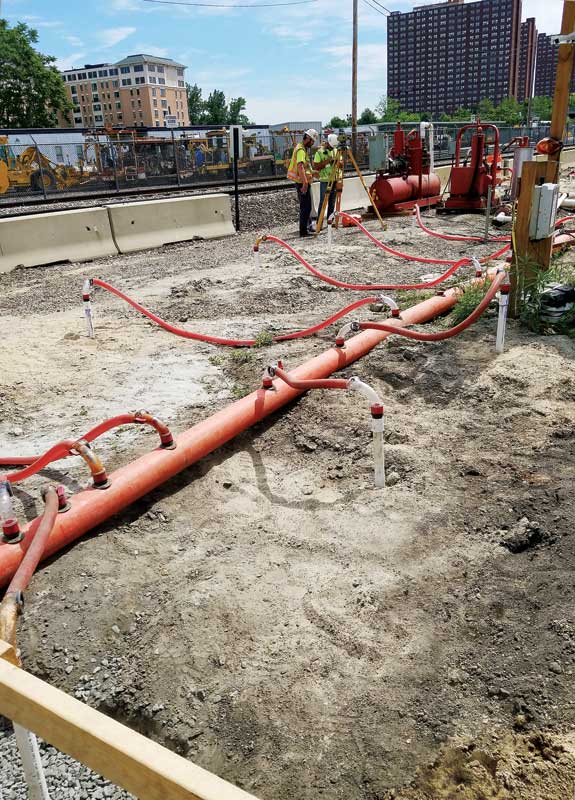
Since pumps in well casings are the main method for removing water from the excavated site, the efficient management of the water to these well casings is critical.
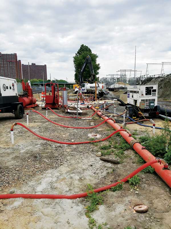
For the dewatering system to be effective, each step in the path must function correctly. The path moves from the below-grade soils, through filters, well casing pipes, and pumps, then into the settlement/treatment tank onsite, and finally to a point of disposal.
It is important to consider a fully functional dewatering pump may continuously draw down the water entering into the well casing, and may cause a site to be considered ‘fully dewatered.’ However, there may still be miscellaneous water on the surface of the excavation that does not reach the well casing due to the permeability of excavation top soils, or blockage of the slits in the well casing, or both without supplementary stone or media drains.
Construction dewatering for waterproofing
In the early planning stages of the project, the process of dewatering a project site should look beyond what is required for structural and shoring requirements, taking into account the requirements of the below-grade waterproofing system. This upfront coordination will result in fewer surprises in the field during construction and, ultimately, a more efficient, better-coordinated, and more successful project.
In addition to structural requirements, more rigorous waterproofing-related items should also be considered regarding construction dewatering, such as:
- selecting and specifying an appropriate shoring system that take into account the requirements of the waterproofing to provide a dry substrate for the application of the waterproofing;
- including post-installation shoring system wall leakage repair recommendations as necessary;
- defining the performance of the dewatering at horizontal and sloped excavations to include providing an adequately dry substrate (i.e. no dampness that would interfere with the membrane installation, adhesives, etc.) for the application of the waterproofing;
- coordinating the shoring system and excavation layout and extents to provide a fully dewatered condition at their junction; and
- providing an efficient, redundant dewatering system that is able to deliver water from points of collection at vertical, sloped, and horizontal extents through to the point of disposal.
If a shoring system is a delegated design component, then coordination between its design (by the shoring sub) and the waterproofing requirements (specified by the architect) is critical.
| CONSTRUCTION DEWATERING REGULATIONS |
|
Governing authorities for the projects regulate construction dewatering, which is generally classified as non-routine, episodic, or other temporary discharge use.* Regulation is by permit, which sets forth the requirements by which the project is allowed to discharge into the sewer system, including testing requirements, the quantity and duration of the dewatering, and discharge fees. Depending on the project conditions and shoring system used, there may be significant discharge fee savings associated with either changing to a more watertight shoring wall system or the repair of excessive shoring leakage to meet the requirements of the below-grade waterproofing substrate, or both. * More information can be found in the San Francisco Public Utilities Commission’s, Batch Wastewater Discharge Requirements (May 2012), and Sanitation Districts of Los Angeles County, Chapter 11—“Hydrology, Water Quality and Public Health” (January 2012). |
Daniel G. Gibbons, PE, associate principal with Simpson Gumpertz & Heger (SGH) specializes in new design, including design consultation and construction administration of building envelope systems. He consults with architects, contractors, and developers on structures ranging from residential to high-rise construction, and works on a variety of building types, including condominiums, hotels, and mixed-use projects. Gibbons investigates existing building envelopes and is involved in new design of a variety of systems, including below-grade waterproofing, plaza deck waterproofing, exterior wall assemblies, balcony waterproofing, window assemblies, and roofing. Gibbons is practice leader for SGH’s Roofing & Waterproofing Practice Group. He can be reached via e-mail at dggibbons@sgh.com[1].
Payal R. Vora, LEED AP, has seven years of experience in the design and investigation of commercial, institutional, and residential buildings for waterproofing issues including roofs, plaza areas, below-grade spaces, and exterior walls. She has consulted with architects, contractors, and building owners on the repair and rehabilitation of contemporary and historic buildings. Vora can be reached at prvora@sgh.com[2].
- dggibbons@sgh.com: mailto:dggibbons@sgh.com
- prvora@sgh.com: mailto:prvora@sgh.com
Source URL: https://www.constructionspecifier.com/construction-dewatering-understanding-its-effect-on-below-grade-waterproofing/