


by Tom Remmele, CSI
Continuous insulation (ci) has been a component of exterior wall assemblies for more than 40 years in North America and even longer in Europe. It has always been the smart way to design wall assemblies from the standpoint of energy conservation and water management. By minimizing energy loss caused by thermal bridging and the risk of condensation caused by water vapor diffusion, exterior ci can improve building durability and benefit the environment.
Standards-writing and regulatory bodies, government agencies, and the building science community are in alignment in viewing exterior ci as a sensible strategy to conserve energy in buildings. The American Society of Heating, Refrigeration, and Air-conditioning Engineers (ASHRAE) has steadily driven energy conservation standards—and hence, the International Energy Conservation Code (IECC)—to ci prescriptive R-value requirements (in combination with stud cavity insulation) as a pathway to greater energy conservation in buildings.
In sponsoring the 2012 IECC code changes, the Department of Energy (DOE) helped achieve the “largest one-step energy efficiency increase in the history of our energy code.” Building Science Corporation identifies the ‘perfect wall’ (i.e. one working in any climate zone), as having ci outbound of the structure. Thus, for the foreseeable future ci is likely to be a fixture in most exterior wall assemblies.
Types of foam plastic ci
Figure 1 summarizes properties of rigid cellular polystyrene and polyisocyanurate (polyiso) thermal insulations as published in ASTM C578-14, Standard Specification for Rigid, Cellular Polystyrene Insulation, and ASTM C1289-14, Standard Specification for Faced, Rigid Cellular Polyisocyanurate Thermal Insulation Board, respectively. Commonly used insulating materials conforming to these property requirements are Type I expanded polystyrene (EPS), Type IV extruded polystyrene (XPS), and Type I, Class 1 or 2 polyiso.
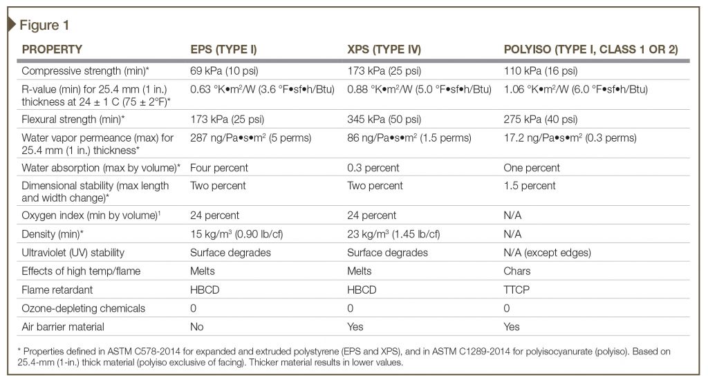
Each insulating material has its own benefits and limitations influencing which one should be used for a given project. For example, EPS is the insulation commonly used in exterior insulation and finish systems (EIFS) because of its dimensional stability, water vapor permeability, and adhesion compatibility with EIFS adhesives and base coats. Due to their higher R-values, XPS and polyiso boards are more commonly used behind brick veneer to allow for thinner wall sections. This becomes important when considering the total thickness of a brick veneer cavity wall with ci and the implications on size and thermal bridging of supporting shelf angles and lintels.
Water vapor permeability of the insulating material can be an advantage or disadvantage. For example, in hot, humid climate zones where vapor drive is predominantly inward, exterior polyiso or XPS insulation can retard inward vapor drive and reduce the potential for condensation on the relatively cold conditioned surface of interior drywall over metal studs. In mixed climates, where vapor drive is both inward and outward for long periods during the course of a year, EPS ci is advantageous because its higher vapor permeability allows water vapor to diffuse, which aids in drying of the wall assembly in the event of condensation.
A wall analysis during design is a valuable tool for selecting the best type of ci material in this regard. Dynamic computer models are a good approach, since they characterize wall assembly hygric performance through seasonal change, but even a simplified steady-state analysis for worst case winter and summer months can be a helpful tool to assist in making material choices for a given wall assembly.
Other things to consider beyond physical properties are jobsite handling, storage, and compatibility with other materials, as well as the construction Type, whether Types I?IV or Type V, and design wind pressure requirements. EPS and XPS have limited ultraviolet (UV) resistance and should not be left exposed to sun for extended periods as the surface will degrade (chalk).
While this degradation has no significant effect on R-value, it can interfere with adhesion of joint treatments, tapes, EIFS base coats, and membrane materials that rely on adhesion to the surface, unless the surface is rasped or sanded to remove the chalked material. Chalking is not an issue when the insulation is ‘faced’ with glass mat facing or aluminum foil facing as with most polyiso boards, although adhesion to the facing materials still has to be evaluated.
Equally important to consider (if not more so) on jobsites is the combustibility of foam plastics. They should be protected from sparks, flame, or any other source of ignition. All foam plastic insulation boards are produced with flame retardant, but they behave differently in the presence of flame; while EPS and XPS melt, polyiso chars.
Despite their combustibility, all these foam plastic insulating materials can be used on buildings required to be of noncombustible construction (Types I?IV) with proper material and ‘end use’ testing to support the proposed assembly. Likewise, they can all be used in wind-resistant assemblies provided they are constrained (i.e. sandwiched) in the negative and positive direction by another material (e.g. sheathing/cladding) capable of resisting design wind pressures. Alternatively, appropriate tests can be performed to determine wind load resistance of the insulation relative to project and/or building code requirements.
Fire safety considerations
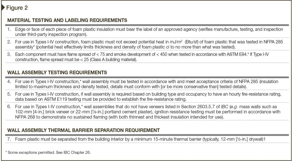
Fire safety in the design of foam plastic-based wall assemblies is an important factor when considering their use. Since such materials are combustible, building codes strictly regulate the use of foam plastics. Chapter 26 of the 2015 International Building Code (IBC) has seven requirements that must be met for foam plastics to be approved for use in walls (Figure 2).
For the design professional, listing and labeling of the insulation by an approved independent third party is the first step in verifying code compliance. Most insulation board manufacturers hold International Code Council Evaluation Service (ICC-ES) evaluation reports (ESRs), or Underwriters Laboratory (UL) or other listings, simplifying verification.
These listings also demonstrate other aspects of code compliance, for example, compliance with flame spread and smoke development criteria to qualify as a Class A building material, or special uses such as below-grade or attic insulation. Other code compliance requirements are more difficult to verify because they involve wall assembly tests that may exist with the insulation board manufacturer, the cladding manufacturer, or, in some cases, with the air barrier/water-resistive barrier (WRB) manufacturer.
Potential heat, a measure of the foam plastic’s stored heat energy, is a function of the type of foam plastic insulation, its thickness, and density. IBC effectively limits potential heat for construction Types I?IV to the insulation thickness and density successfully tested in the National Fire Protection Association (NFPA) 285, Standard Fire Test Method for Evaluation of Fire Propagation Characteristics of Exterior Non-load-bearing Wall Assemblies Containing Combustible Components.
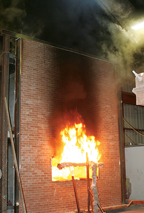
NFPA 285 is a qualifying wall assembly test for the use of foam plastic in wall assemblies of Types I, II, II, or IV construction. As a ‘worst-case’ surrogate for exterior wall fires, the test addresses the effects of a simulated fire in an interior room and vertical flame propagation from floor-to-floor and room-to-room vertically and laterally. An example of an assembly that meets NFPA 285 acceptance criteria is shown in Figure 3, and the actual test is depicted in Figure 4.
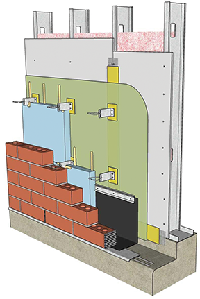
While the test enables approval of the assembly in Types I?IV construction, it also establishes limits—maximum allowable thickness and density of insulation and detailing around the opening that must conform to (or be more conservative, from a fire protection standpoint) what was tested. Test results can sometimes be extended to other claddings or backup wall construction when evaluated by a qualified fire protection engineer.
For example, in Figure 3, the results of the fire tests with masonry veneer over steel stud wall construction were extended to backup wall construction of concrete or concrete masonry unit (CMU) in lieu of steel stud with gypsum sheathing. Once again, ICC-ES evaluation reports can be a valuable resource for the design professional to know what assemblies have been tested and meet acceptance criteria, or where results of tests have been extended, evaluated, and recognized by ICC-ES.
NFPA 285 is not the only assembly test to be considered. ASTM E119-12a, Standard Test Methods for Fire Tests of Building Construction and Materials, is necessary when walls are required to have an hourly fire-resistance rating—a common requirement for commercial office, institutional, and some retail and multi-family type construction. The test evaluates the ability of the assembly to resist temperature rise, collapse, flaming, or ignition on the unexposed side of the assembly.
If the assembly is asymmetrical, it must be tested from both sides—in other words, with the fire originating from the interior or exterior. Further, the effects of a hose stream (used to provide additional structural evaluation) are evaluated to ensure the unexposed side remains intact and there is no breach or collapse of the assembly as a result of the hose stream.
Engineering analysis or modeling by a qualified fire protection engineer can be done to qualify substitute materials or to make minor revisions to what was tested to provide the design professional with a wider range of material options for the wall assembly. For example, if an hourly rating is achieved with a frame wall assembly with gypsum sheathing on the exterior and gypsum wall board on the interior, it is readily assumed a ‘mass wall’ fire-resistive wall construction (e.g. 152-mm [6-in.] cast-in-place concrete or 203-mm [8-in.] CMU) would provide equal or better resistance than the frame wall with the same exterior ci and cladding assembly. ICC-ES evaluation reports, UL listings, and Gypsum Association’s (GA’s) Fire Resistance Design Manual are valuable resources for the design professional to identify tested fire-resistance rated wall assemblies.
The last of the assembly tests is NFPA 268, Standard Test Method for Determining Ignitability of Exterior Wall Assemblies Using a Radiant Heat Energy Source. The test evaluates a wall assembly’s susceptibility to ignite from the radiant heat produced by a fire in an adjacent building. It is an important test for EIFS and other foam plastic-based wall assemblies that do not conform to one of the six wall covering exceptions listed in Section 2603.5.7 of the 2015 IBC:
- minimum 15-minute thermal barrier;
- minimum 25-mm (1-in.) of concrete or masonry;
- at least 9.5-mm (3/8-in.) glass-fiber-reinforced concrete (GFRC);
- metal-faced panels meeting the prescribed composition and thickness;
- minimum 22.2-mm (7/8-in.) stucco; and
- minimum 6-mm (1/4-in.) fiber cement lap, panel, or shingle siding.
A final requirement of the code for all types of construction is separation of the combustible foam plastic insulation from interior space with a 15-minute thermal barrier, typically 13-mm (1/2-in.) interior drywall or exterior gypsum sheathing. Commercial attic space or the interior wall area above suspended ceilings must have this 15-minute thermal barrier in place on the interior if it does not exist on the exterior side of the wall to separate the foam plastic insulation (with some exceptions permitted in the 2015 IBC’s Section 2603.4.1). Between-the-stud fiberglass batt insulation does not count as a thermal barrier since it is discontinuous.
Thus, building codes strictly regulate the use of foam plastics in wall assemblies. Manufacturers of wall assembly components—cladding, ci, air barrier, and sheathing—must demonstrate compliance with these requirements. ICC ESRs are an excellent resource to facilitate verification of wall assembly compliance.
Moisture-related durability considerations
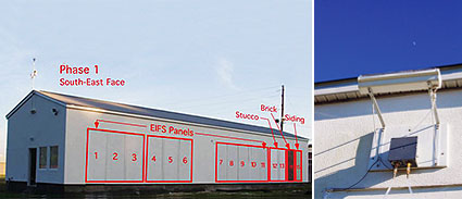
One of the ways exterior ci can help in managing water is by changing the location of the dewpoint in cold climate zones so water vapor diffusion condensation potential is minimized or eliminated. Continuous insulation can also aid in controlling moisture in hot humid climate zones as demonstrated in recent research conducted by the US DOE and the EIFS Industry Members Association (EIMA). The research compared the hygrothermal performance of various wall assemblies—EIFS, stucco, brick, and fiber cement siding (15 assemblies in total)—installed on a test hut (Figure 5) exposed to natural weather in Hollywood, South Carolina (Climate Zone 3A).
Temperature, heat flux, relative humidity (RH), and moisture content measurements were taken 24 hours a day with sensors placed in the wall panels. After a little more than a year of exposure, a flaw (i.e. opening) was created in some of the wall panels to introduce rainwater onto the plane of the WRB behind the cladding. The cladding with ci performed the best from the standpoint of temperature and moisture control as measured by the heat flux sensor on the inside face of interior gypsum wallboard and the relative humidity sensor on the face of the wall sheathing directly behind the WRB (Figure 6).
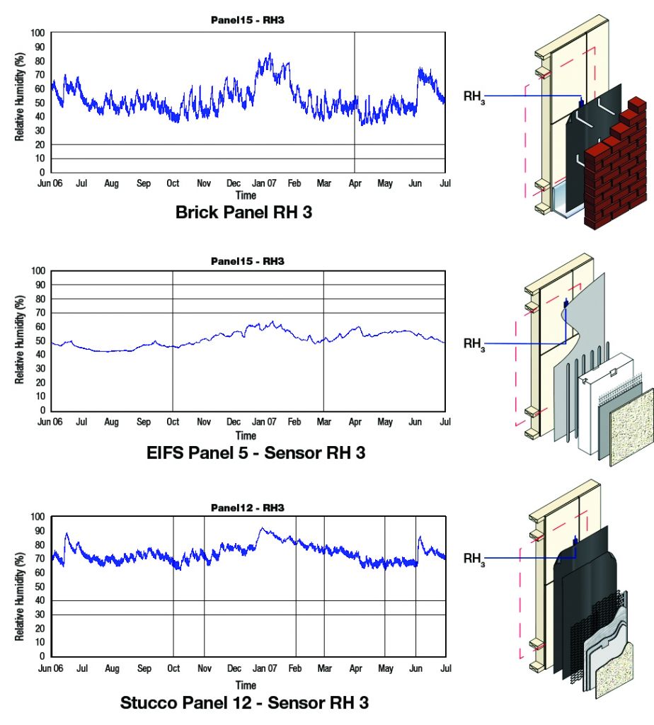
The closer the heat flux sensor stayed to the zero base line (which would represent constant interior temperature), the better the assembly’s thermal performance. An average monthly relative humidity of below 80 percent was considered acceptable based on ASHRAE STP 160, Criteria for Moisture-control Design Analysis in Buildings. The ci assembly proved not only to be best from a thermal standpoint, but also kept wall components dry, even when rain was deliberately directed into the assembly during the second year of exposure. This is important not only from the standpoint of durability, but also because insulation, if it stays moist, loses some of its insulating value.
Key factors in the moisture control success of the ci assembly were:
- exterior ci kept wall sheathing above the dewpoint during winter;
- combination of low water absorption exterior finish materials and relatively low water vapor permeability of the insulation prevented high exterior RH in summer from significantly increasing the sheathing’s relative humidity;
- seamless fluid-applied air barrier/WRB behind the cladding was effective in resisting air leakage (and condensation potential) and was unaffected by the rain introduced into the wall during the second year of exposure (the other claddings had paper WRBs); and
- drainage feature of the ci assembly prevented excess amounts of rain from accumulating in the assembly.
Conclusion
As building codes have evolved to the point where ci is now mandatory for many wall assemblies, rigid foam plastic ci wall assemblies have become more prevalent than in the past. They have special design considerations that need to be addressed at the design stage with an awareness of what the building code requires in relation to the use of foam plastics and their effects on the physics of the wall construction, as well as design details.
While this feature looked at the basic types of materials available, and focused on fire safety and moisture-related durability, this author is also developing another technical article that explores the added complexity of design details, along with structural considerations, environmental impacts, and cost control for a future issue of The Construction Specifier.
Tom Remmele, CSI, is the director technical services/R&D for Sto Corp., a manufacturer of air barriers, coatings, exterior insulation and finish systems (EIFS), and stucco products. He has held technical management positions in the construction industry for more than 25 years. Remmele is a past Technical Committee chair of the EIFS Industry Members Association (EIMA). He can be reached at tremmele@stocorp.com.


I appreciate your information on the fire safety considerations concerned with this type of insulation. I was wondering about this specifically, and you answered a lot of my questions. I have very little experience with this type of this, but I want to insulate a barn on my property so that my dogs can stay there in the winter. Should I attempt this job myself or contact a professional?