Continuing education on continuous insulation

by Tom Remmele, CSI
Continuous insulation (ci) has been a component of exterior wall assemblies for almost a half-century in North America. By minimizing energy loss caused by thermal bridging and the risk of condensation caused by water vapor diffusion, exterior ci can improve building durability and benefit the environment. However, using rigid foam plastic comes with certain design considerations that must be reviewed early in the design process.
In the February 2015 issue of The Construction Specifier, this author wrote a piece entitled, “Continuing Education on Continuous Insulation: Design Considerations for Rigid Foam Plastic Insulation in Exterior Walls.” That feature looked at the basic types of materials available, and focused on fire safety and moisture-related durability. Now, this article serves as a sequel of sorts, examining the added complexity of design details, along with structural considerations, environmental impacts, and cost control.
Design detailing considerations
When exterior ci is added to a wall assembly, design details can become more complicated because of the sometimes competing or conflicting design requirements of fire safety, insulation continuity, aesthetics, installation practicality, cost control, and water management.
While exterior ci functions to minimize or prevent water vapor diffusion condensation in wall assemblies, condensation caused by air leakage (which is beyond this article’s scope) is a greater threat to durability, and even greater is leakage of rainwater into walls. Preventing rain’s intrusion and accumulation of moisture in walls is critically important—perhaps even more so in exterior foam plastic ci wall assemblies—because the ci component can limit drying of the assembly.
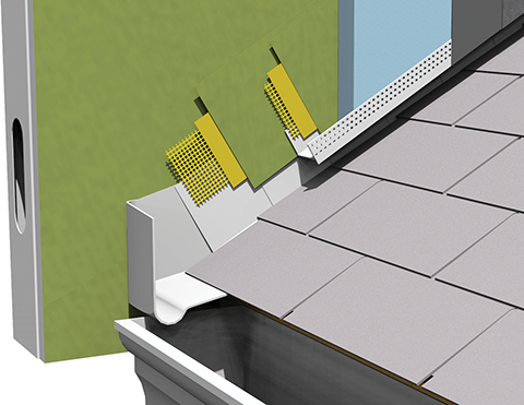
Design details that deflect rain and prevent water entry into walls are the best preventative approach. For example, the need for diverter flashing is critical at roof/wall intersections since the insulation and cladding project well beyond the roof intersection (Figure 1). The omission of this diverter flashing (and other flashing components) was one of many construction defects that caused water intrusion damage to wood-frame homes clad with exterior insulation and finish system (EIFS), stucco, wood, and other wall claddings over a decade ago in North Carolina.
Establishing a drain plane in the assembly and how and where flashing integrates with the drain plane, particularly with mixed claddings, requires thoughtful detailing. Figure 2 shows flashing integrated in the typical location over sheathing and behind the insulation for the EIFS assembly and similarly for the masonry wall.
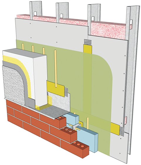
While this has the advantage of keeping the air barrier/water-resistive barrier (WRB) in the same plane (and facilitating its detailing), the EIFS has its drain plane behind the insulation and the masonry has its cavity outbound of the insulation. The two drain planes/cavities are out of plane; water from one should not be directed into the other. Thus, the EIFS assembly is ‘flashed’ to the exterior above the masonry wall to redirect any incidental water that gets behind the EIFS (from a crack or other breach) to the exterior.
The situation could be worse if the masonry wall were above the EIFS cladding. EIFS has historically been proven as an effective barrier against water infiltration. On the other hand, masonry walls have been described as “reservoir” claddings where substantial amounts of water are expected to get into and through the masonry veneer, resulting in elevated moisture levels in the cavity (Figure 2). Water in the masonry wall cavity should not be directed into the drainage plane behind the EIFS cladding. Once again, ‘flashing’ to the exterior above the dissimilar cladding would be appropriate.
Perhaps the most critical detail of any wall assembly is the window/opaque wall interface detailing, since this is the location where multiple components produced by multiple manufacturers (and installed by multiple trades) typically come together. Additionally, it is often a repeated condition that is distributed over the area of building elevations, so the effects of any errors here can easily be compounded.
Sign up for our weekly newsletter
Architectural materials and methods delivered right to your inbox
- CSI News and Notes: CSI Foundation’s construction camp; CSI spring exam; and more
- CSI News and Notes: CSI’s credentials; CSI conference theme; and more
- To be specific – CSI supports young AECO professionals
- CSI News and Notes: CSI’s foundation scholarships, national conference, and Crosswalk
- CSI News and Notes: AI’s impact; CSI 2024 conference, and more
Related Products
Read the Latest Issue