

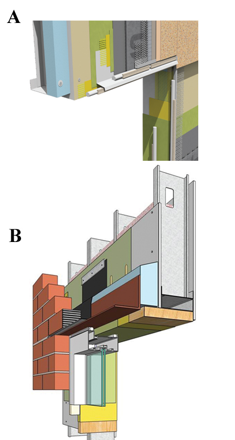
Issues of sequencing of trades, compatibility of adjoining materials, and window, sealant, and cladding termination detailing are all in play at this location. Further, it is the critical location evaluated in National Fire Protection Association (NFPA) 285, Standard Fire Test Method for Evaluation of Fire Propagation Characteristics of Exterior Non-load-bearing Wall Assemblies Containing Combustible Components. Two assemblies are shown in Figure 3, both having met the NFPA 285 acceptance criteria. In Figure 3A, the insulation was placed inbound of the sheathing. This has the advantage of ‘normalizing’ construction sequencing since the sheathing with air barrier/WRB, then window installation, and then cavity component and cladding installation mimic what would typically occur without ci.
This also eliminates ‘blind’ fastening, which can occur when the insulation is installed over the sheathing without marking stud lines. The only trade-off here is the rough opening has to be oversized to accommodate the sheathing return into it. The return of the gypsum sheathing into the opening in tandem with the fire-protective stucco cladding on the face of the wall protects the foam insulation from fire exposure.
Another important part of this detail related to fire safety is the requirement for a 15-minute thermal barrier (typically 13-mm [1⁄2-in.] drywall on the interior side of the wall separating the foam plastic from the interior space). In Figure 3B, a masonry veneer cavity wall, the insulation is placed in the more typical location outbound of the sheathing. In this case, the cavity is blocked with fire-retardant-treated (FRT) solid wood to protect the cavity and combustible ci.
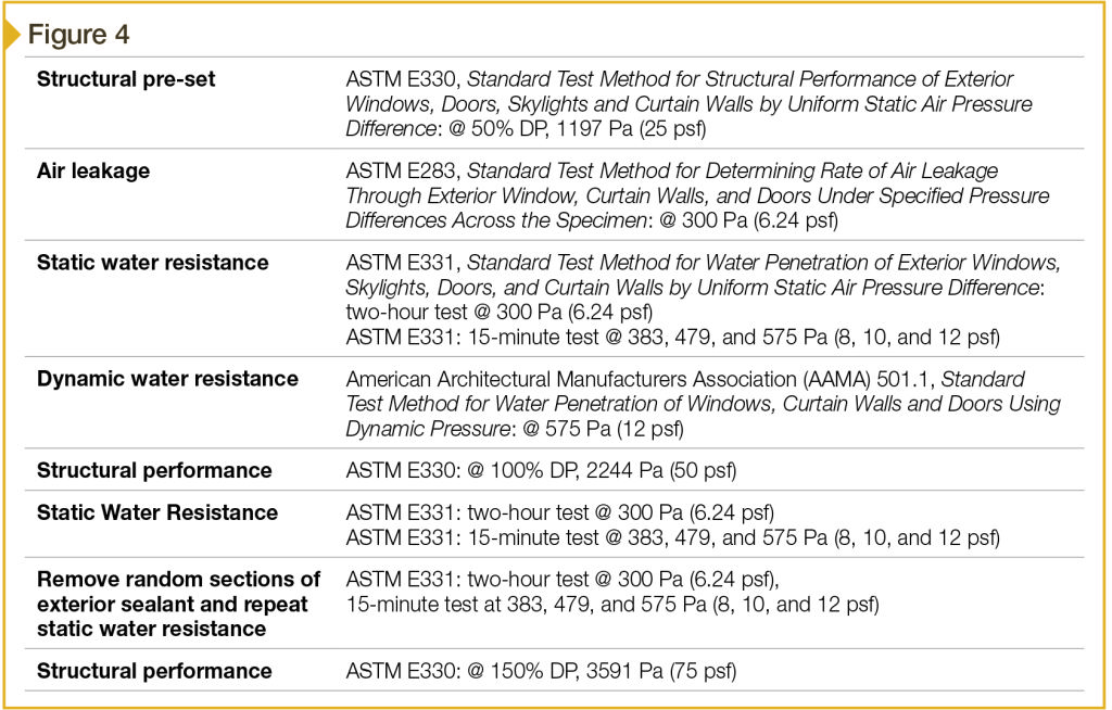
Once detailing is fully resolved on paper, mockup construction and testing is a good idea to verify waterproofing integrity of the window/opaque wall interface detailing. The materials, methods, and planned sequencing should be used in the mockup to verify air leakage resistance, as well as water penetration resistance (or control of water penetration with flashing), followed by structural loading to verify performance with appropriate safety factors in relation to design wind pressures. A sample test protocol is shown in Figure 4. The sequence of progressively more severe testing can provide insight into corrective measures needed for construction detailing and where components may need to be reinforced, reintegrated, or re-evaluated in the wall assembly design.
One other important detail area to consider when using foam plastic in wall assemblies is at grade. In Chapter 26, Figure 2603.8, the International Building Code (IBC) restricts foam plastic to use above grade in areas of the country prone to termite infestation. However, there is a conflict since significant energy loss can occur through the foundation wall or slab edge when left uninsulated. Some exceptions are permitted in the code to allow ‘work-arounds.’ For example, if the building structure is entirely made up of noncombustible materials such as concrete or masonry, or preservative-treated wood, or if an “approved method of protection” (i.e. termite-shield) is provided, the foundation wall or slab edge can be insulated. Alternatively, the interior side of basement walls can be insulated.


I would like to read the article about CI and wish to receive Continuing Ed credits (via quiz?) but do not know how to register.
Please advise.
Reference: Figure 6, the drainage mat dimensional conversions are incorrect. Assuming the mat is 1/4 in thick, it would be 6.35 mm thick.
Continuous insulation seems like a good option for year round energy savings. As I was reading, I noticed that it seems to be an option primarily for businesses. As a homeowner, continuous insulation seems like it would be a good thing to have in my home. Is continuous insulation an option to use in homes as well, or is it just not practical due to size or other factors?